C.P. SENTINEL AUTOMATIC TYPE CATHODIC PROTECTION RECTIFIER MANUAL
INTEGRATED RECTIFIER TECHNOLOGIES, INC.
Doc #: APC0010
Rev. 3.0, November, 2004
Page 11 of 22
B. PROGRAM MODES (JP231) USE WITH FIRMWARE VERSION 16C622AS-1.00
C: EXTERNAL INTERRUPT (JP241)
D: POTENTIAL MODE SETTINGS
E: VOLTAGE RANGE SETTINGS: “JPR411”
Header “JPR411” is factory set to determine the available output range of voltage control.
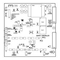
OTHER CONTROLLER PARTS & FUNCTIONS
FUSE: “F601” is located on the circuit board near the board-mounted control transformer.
This a 0.125 ampere, slow-blow type of 5mm x 20mm metric style fuse. Replace with same
fuse type and rating.
POWER ON LED: Controller “POWER ON” operation is indicated by “LED231”, Yellow
WIRING CONNECTORS: “TB101” & “TB102”. These are 14-pin plug on connectors. Ensure
all wiring connections are secure by tightening the screw terminals on these connectors.
“JP231” SETTING FUNCTION COMMENT
JP231 – 1 (TRIG)
NOT SUPPORTED NOT USED
JP231 – 2 (Rsamp)
INSTALLED: Reference Electrode
Sampled just prior to SCR Gate-on
DEFAULT: Use in IR-Free
mode & Choke Filtering
JP231 – 2 (Rsamp)
REMOVED: Reference Electrode Sampled
after Zero-Crossing AC waveform
Use with AC Interference
JP231 – 3 (SF A)
Doubles SCR Gating “ON” & “OFF” times INSTALLED (DEFAULT)
JP231 – 4 (SF B)
Doubles the “SF-A” SCR Gating “OFF” time INSTALLED (DEFAULT)
“JP241” SETTING FUNCTION
JP241 PINS 1 - 2
Normally Closed contacts = Rectifier output current (Optional Setting)
JP241 PINS 2 - 3
Normally Open contacts = Rectifier output current (Default Setting)
JUMPER FUNCTION – DESCRIPTION COMMENT
JPR311, PINS 1-2
“Loss of Reference Shutdown” Enabled INSTALLED
JPR331, PINS 1-2
Select Type of Reference Cell = CU-CUSO
4
or Ag-CL DEFAULT
JPR331, PINS 2-3
Select Type of Reference Cell = ZINC OPTIONAL
JPR341, (CLOSED)
JPR362, (OPEN)
Select Low Range (Max. Potentials less than ± 3.0 Volts) OPTIONAL
JPR341, (OPEN)
JPR362, (CLOSED)
Select High Range (Maximum Potentials > than ± 3.0 Volts) DEFAULT
JPR361, PINS 1-2
Select Continuous “ON-Potential” Control & Sampling DEFAULT