C.P. SENTINEL AUTOMATIC TYPE CATHODIC PROTECTION RECTIFIER MANUAL
INTEGRATED RECTIFIER TECHNOLOGIES, INC.
Doc #: APC0010
Rev. 3.0, November, 2004
Page 10 of 22
CAUTION!!
Do NOT attempt to alter the settings of any other trim pots on the controller board. These
are factory calibrations and tampering with these settings could jeopardize proper operation
and scaling of the SENTRY Controller.
CONTROLS:
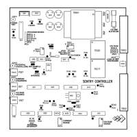
Voltage, Current, and Potential settings are adjusted via three potentiometers available on the
SENTRY Controller. These potentiometers are 20-Turn trim-pots located at the end of the
controller board opposite the wiring connectors. (Refer to Figure 1.0, Page 9).
VOLTAGE:
Rectifier output voltage (or Voltage Limit) is set by potentiometer “RV411”.
Rectifier operation in Voltage Mode or Voltage Limit will be indicated by the Red LED
“LED491”, adjacent the Voltage Set Potentiometer.
CURRENT:
Rectifier output current (or Current Limit) is set by potentiometer “RV431”.
Rectifier operation in Current Mode or Current Limit will be indicated by the Green LED
“LED492”, adjacent the Current Set Potentiometer.
POTENTIAL
: On rectifiers equipped with this option: Rectifier Structure to Reference
Electrode Potential is set by potentiometer “RV451”, in conjunction with the “Press-to-
Set/Actual” selector switch. Rectifier operation in the Potential Mode will be indicated by the
Yellow LED “LED493”, adjacent the Potential Set Potentiometer. Both Potential Set Point and
Actual Structure-Reference Electrode potential may be read on the rectifier’s potential meter
via the “Press-to-Set/Actual” selector switch.
JUMPER SETTINGS:
The SENTRY Controller is designed to adapt and accommodate a wide variety of field
installations and control situations. To make this accommodation easier, please review the
following Jumper functions and settings:
A. INPUT VOLTAGE SELECTION (JP601, JP602, & JP603)
INPUT
VOLTAGE
JP601 JP602 JP603 COMMENT
115 VAC
INSTALLED INSTALLED OMITTED DEFAULT POSITION
230VAC
OMITTED OMITTED INSTALLED OPTIONAL POSITION
NOTE:
Depending upon the model and/or configuration of the rectifier ordered, one or more of
these potentiometers may be mounted external of the controller board on the rectifier
instrument panel. Consult your Rectifier Specification Sheet.