PB 110 - 16
• DESCRIZIONE DEI COMANDI
( SPECIFICA PER MODELLO 110 E )
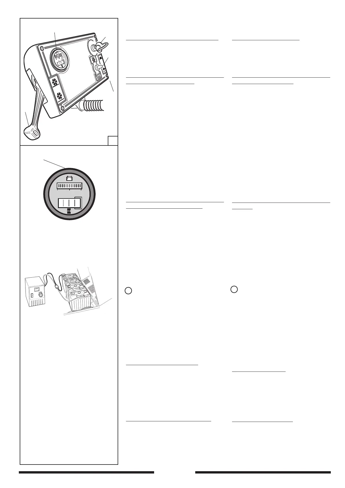
CHIAVE AVVIAMENTO part. 1 Fig. 11
La chiave di avviamento part.1 Fig.11
serve per mettere in tensione l’impianto
elettrico della macchina
INDICATORE CARICA BATTERIE-
CONTAORE part. 2 Fig. 11
Il part. 2 Fig. 10 indica la carica della
batteria:
100% luce ROSSA ➞ batteria CARICA
75% luce ROSSA ➞ batteria CARICA
50% luce ROSSA ➞ batteria CARICA
25% luce ROSSA ➞ batt. RISERVA
0% luce ROSSA lampeggiane ➞
batt.SCARICA ➞ RICARICARE
• DESCRIPTION OF CONTROLS (
SPECIFICATION FOR MODEL 110 E )
KEY SWITCH part. 1 Fig. 11
This switch, item 1, Fig. 11 is used to provide
power to the sweeper’s electrical system.
BATTERY CHARGER READOUT - HOUR
COUNTER Item. 2 Fig. 11
This device provides the following
information:
100% RED light
➞battery CHARGED
75% RED light
➞battery CHARGED
50% RED light ➞battery CHARGED
25% RED light ➞battery on
RESERVE
0 % RED light ➞battery FLAT
➞ RECHARGE
1
2
3
5
4
11
Part. 2
24 V - 30 A/h
INTER RUTTORE AVVIA MENTO -
SCUOTIFILTRO A 3 POSIZIONI
Part. 3 Fig. 11, interruttore a due funzioni.
Nella posizione 1 serve per avviare e
fermare il motore della macchina che aziona
le spazzole e la ventola ad un regime di
giri costante. Nella posizione 3, serve a
scuotere elettricamente il ltro per mezzo
di un vibratore; deve essere premuto per
almeno 6/7 volte per una durata di 5÷6
secondi per volta.
IMPORTANTE: Questa operazione deve
essere eseguita prima di iniziare il lavoro,
e prima di svuotare il cassetto di raccolta
con motore spento.
LEVA SPAZZOLA CENTRALE
La leva Part. 4 Fig. 11 serve per alzare ed
abbassare la spazzola centrale.
La spazzola centrale è autolivellante e
autoregolante, non necessita pertanto di
alcuna regolazione.
COMANDO SPAZZOLA LATERALE
La leva Part. 5 Fig. 11 serve per alzare ed
abbassare la spazzola laterale.
➞
➞
➊
AVVIAMENTO MOTORE SPAZZOLE-VENTOLA
➋ FOLLE
➌ SCUOTIFILTRO
3-POSITION START - FILTER SHAKER
SWITCH
Item 3 Fig. 11. Two-function switch. In po-
sition 1 it will start and stop the sweeper’s
motor that activates the brooms and fan at
a steady state. On position 3 it electrically
shakes the lter by means of a vibrator; it
must be pressed at least 6 to 7 times for 5-6
seconds each time.
IMPORTANT: This operation should be
done before starting work and before
emptying the hopper with the motor
off.
MAIN BROOM LEVER
Item 4, Fig. 11. This lever is used to raise
and lower the main broom. The main broom
is self-levelling and self-adjusting so needs
no adjusting.
SIDE BROOM CONTROL
Item 5, Fig. 11. This is used to raise and
lower the side broom.
➞
➞
➊ BROOM-FAN MOTOR STARTER
➋ NEUTRAL
➌ FILTER SHAKER