osition Control
Position control is used when attachin
implements and other operations requirin
the imple-
ment to be kept at a constant hei
round.
It is also used with tool bars havin
lexible row units
and implements equipped with
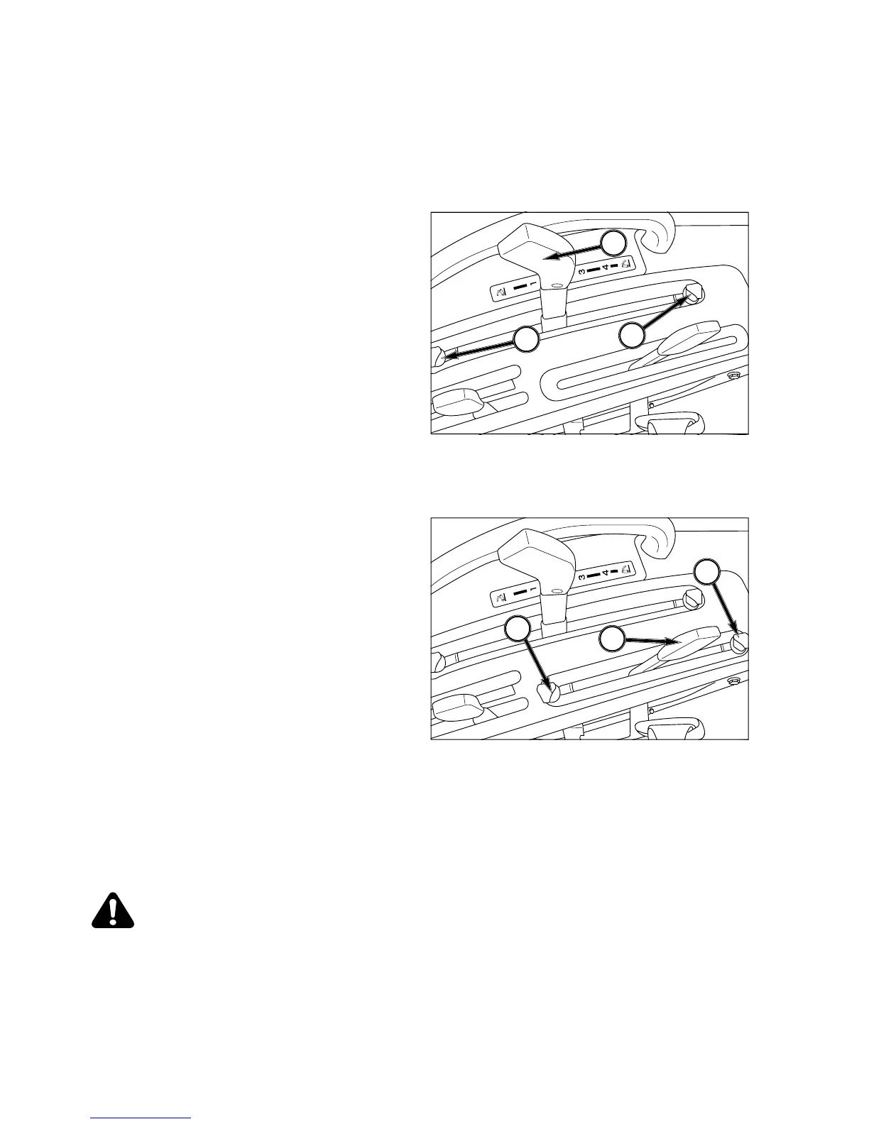
The position control lever maintains hitch
osition at a constant hei
ht in relation to the tractor. As
the position control lever, 1, is moved backward, hitch
and implement are raised. Movin
the lever forward
will lower hitch to selected position. Each lever settin
ic hitch and implement position.
The front lever stop, 2, can be set to contact the posi-
tion control lever in the implement work position. This
nables the implement to be returned to the identical
ter the hitch has been raised
, etc.
The rear lever stop, 3, can be set to limit raisin
ht, if required.
NOTE: When starting engine, ensure implement i
owered to the ground and lever is
orward.
This reduces load on starter due to hitch tr
o raise when engine is cranked.
FIG. 4-41
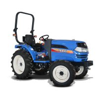
n the tractor and imple-
ment in the field and move the position control lever,
1, forward
the position control lever and set the ad
tops, 2, and 3, as desired.
When turnin
, move position control lever backward
to raise the implement and permit
turn. Return the implement to the work
the position control lever to the
ainst the stop.
To finish work and transport, pull position control lever
to the “draft” or pull of
implements. This provides consistent load
on Tractor and provides wei
ht transfer to Tractor rear
wheels to reduce wheel slippa
e.
Lever stops, 2, and 3, can be ad
osition control lever, 1,
when attachin
NOTE: When starting engine, ensure implement i
owered to the ground and both levers are
ing to raise when engine is cranked.
FIG. 4-40
FIG. 4-4