EasyManuals Logo

Iseki TH4335 User Manual

Iseki TH4335
113 pages
To Next Page IconTo Next Page
To Previous Page IconTo Previous Page
Page #66 background imageLoading...
Page #66 background image
OPERATION
63
E
XTERNAL AUXILIARY HYDRAULIC
S
Auxiliar
y
h
y
draulics can be installed to operate imple-
ments requirin
g
an external h
y
draulic source
f
or oper-
ation. Kits are available as sin
g
le-spool
(
one auxiliar
y
c
ircuit
)
or two-spool
(
two h
y
draulic circuits
).
2 spools:
S
TD
f
or rear R
O
P
S
model.
1 spool: STD for center R
O
PS model.
NOTE: Center ROPS model can equip the sencon
d
s
pools as the option.
WARNING: When usin
g
a loader attach-
m
ent, to avoid serious in
j
ur
y
or death due
to fallin
g
loads resultin
g
from inadvertent
r
aisin
g
or roll-back of the loader, DO NOT
c
onnect loader h
y
draulics to an
y
tractor
a
uxiliar
y
valve that has detents which
c
annot be locked out or removed, exce
p
t
f
or the float function in the loader lower
c
ircuit. If the tractor is e
q
ui
pp
ed with such
a
valve, a dedicated, properl
y
confi
g
ured
l
oader valve MUST be installed
.
FIG. 5-50
:
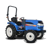
The control lever, 1, controls implement
r
aisin
g
or lowerin
g
when the first set of remote cou-
p
lers are used. The control lever, 2, controls implement
when second set o
f
remote couplers are used
(
two-
s
pool kit onl
y)
.
C
ontrol lever
(
s
)
are sprin
g
-loaded to center neutral
p
osition,
f
rom normal raise or lower positions.
Push the levers
f
ull
y
f
orward to hold in a detent pro-
vidin
g
a float position. Float position is used for loader
and blade operations to allow the bucket or blade to
f
loat on top o
f
the sur
f
ace. The
f
loat position is also
u
sed in some implement applications.
FIG. 5-51
:
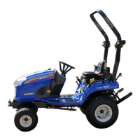
Remote couplers are located at the rear o
f
the tractor.
(
Coupler
(
s
)
: Consult with
y
our dealer
)
Please procure the couplers a
t
The coupler set, 1, is controlled b
y
the inside control lever.
The coupler set, 2, is controlled b
y
the outside control lever.
Implement hoses must be connected to each coupler set.
When the speci
f
ic control lever is pulled backward,
the implement raises and, when pushed
f
orward, the
implement lowers. Male coupler tips
(
on implement
h
oses
)
must be compatible with tractor couplers, and
must also be inserted full
y
and locked into tractor cou-
p
lers to operate correctl
y
.
CAUTION: Alwa
y
s lower implement to
g
round, shut off en
g
ine and relieve s
y
s-
tem pressure
(
b
y
operatin
g
control levers
with en
g
ine off
)
before connectin
g
or
d
isconnectin
g
implement hoses
.
FIG. 5-50
FIG. 5-5
1

Table of Contents

Questions and Answers:

Question and Answer IconNeed help?

Do you have a question about the Iseki TH4335 and is the answer not in the manual?

Iseki TH4335 Specifications

General IconGeneral
BrandIseki
ModelTH4335
CategoryTractor
LanguageEnglish

Related product manuals