Home
Isel
Controller
iMC Series
Page 11
Isel iMC Series - Page 11
24 pages
Manual
Save Page as PDF
To Next Page
To Next Page
To Previous Page
To Previous Page
Loading...
iMC-B / iMC-
V
Operating Instructi
on
page -
11
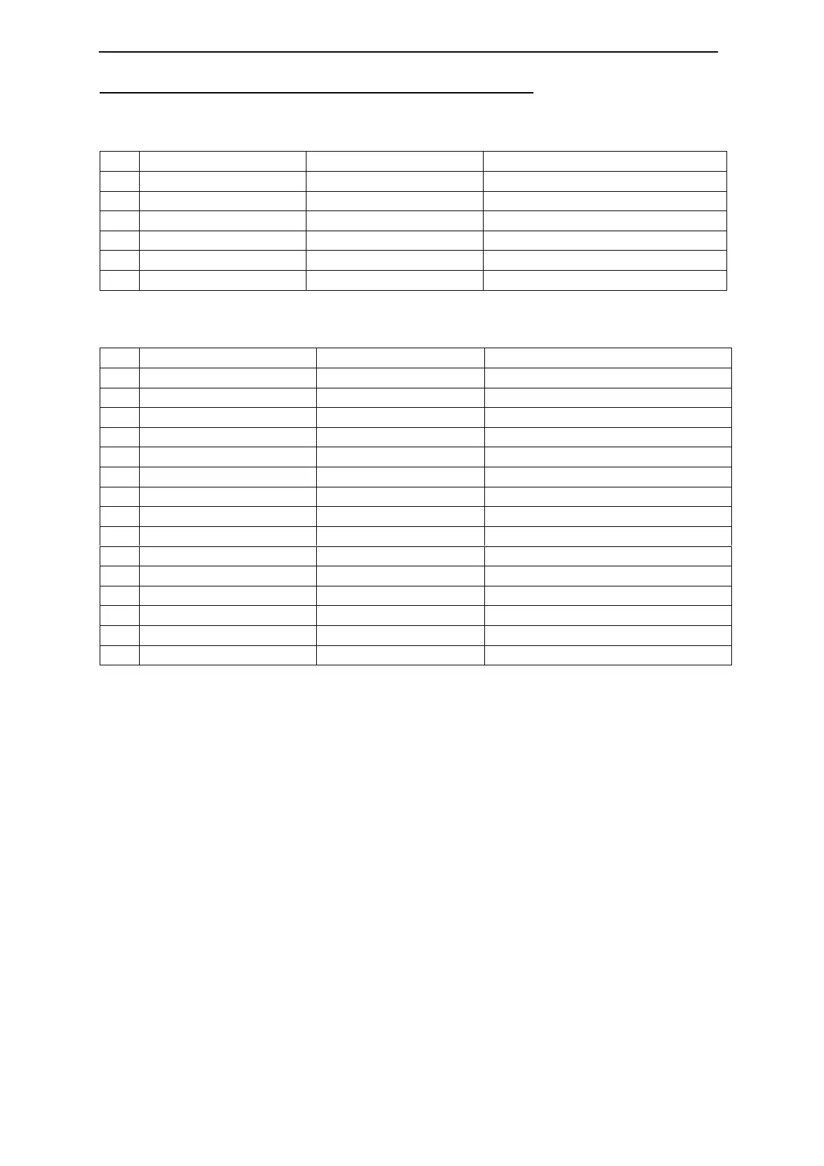
iMC-V connectors for motor-, encoder- and signal lines
motor connector (X, Y, Z, A, B, C), 6-pin M23 socket
pin
signal
line color
description
1
U
black 1
motor phase U
2
V
black 2
motor phase V
3
W
black 3
motor phase
W
5
Brake
brown
motor brake
6
Brake_GND
white
motor brake GND
9
PE
yellow / green
protected earth (PE)
encoder/ signal connector, 15
-pin Sub-D socket
pin
signal
line color
description
1
HALL_A _IN
yellow
Hall signal A
2
VCC_Encoder
red
digital +5V DC
3
/ENC_Z
orange / black
encoder line /Z
4
/ENC_B
brown / black
encoder line
/B
5
/ENC_A
grey / black
encoder line /A
6
VCC_Logic
logic +24V DC
7
LIMIT_S
W
1
limit switch 1
8
GND_24V
Logik GND
9
HALL_B_IN
white
Hall signal B
10
D_GND
black
digital GND
11
ENC_Z
orange
encoder line Z
12
ENC_B
brown
encoder line B
13
ENC_A
grey
encoder line A
14
HALL_C_IN
green
Hall signal C
15
LIMIT_S
W
2
limit switch 2
10
12
Table of Contents
Main Page
Default Chapter
3
Table of Contents
3
1 Introduction
4
Safety Symbols
4
Safety Instructions
5
2 Controller Types
6
3 Technical Data
7
4 Hardware Description
8
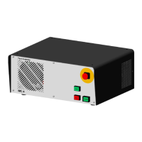
Controller Front Side IMC-B / IMC-V
8
Controller Back Side IMC-B / IMC-V
10
Assembly IMC-B / IMC-V
16
5 Initial Operation
17
6 Software
18
Installing Setup Software
18
Pronc / Remote Installation and First Steps
20
7 EC - Declaration of Conformity
23
8 Bibliography
24
9 Index
24
Related product manuals
Isel CSD 405-IMC
4 pages