iMC-B / iMC-V Operating Instruction
page - 12
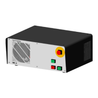
➁ hand control unit - 25-pin Sub-D (optional version)
This connector is only available on controller without integrated function keys in the
case front.
It is possible to connect function keys (switches, buttons) from:
- an external hand control unit
- an isel CNC control panel
with the corresponding connectors on the security circuit module inside the controller
case.
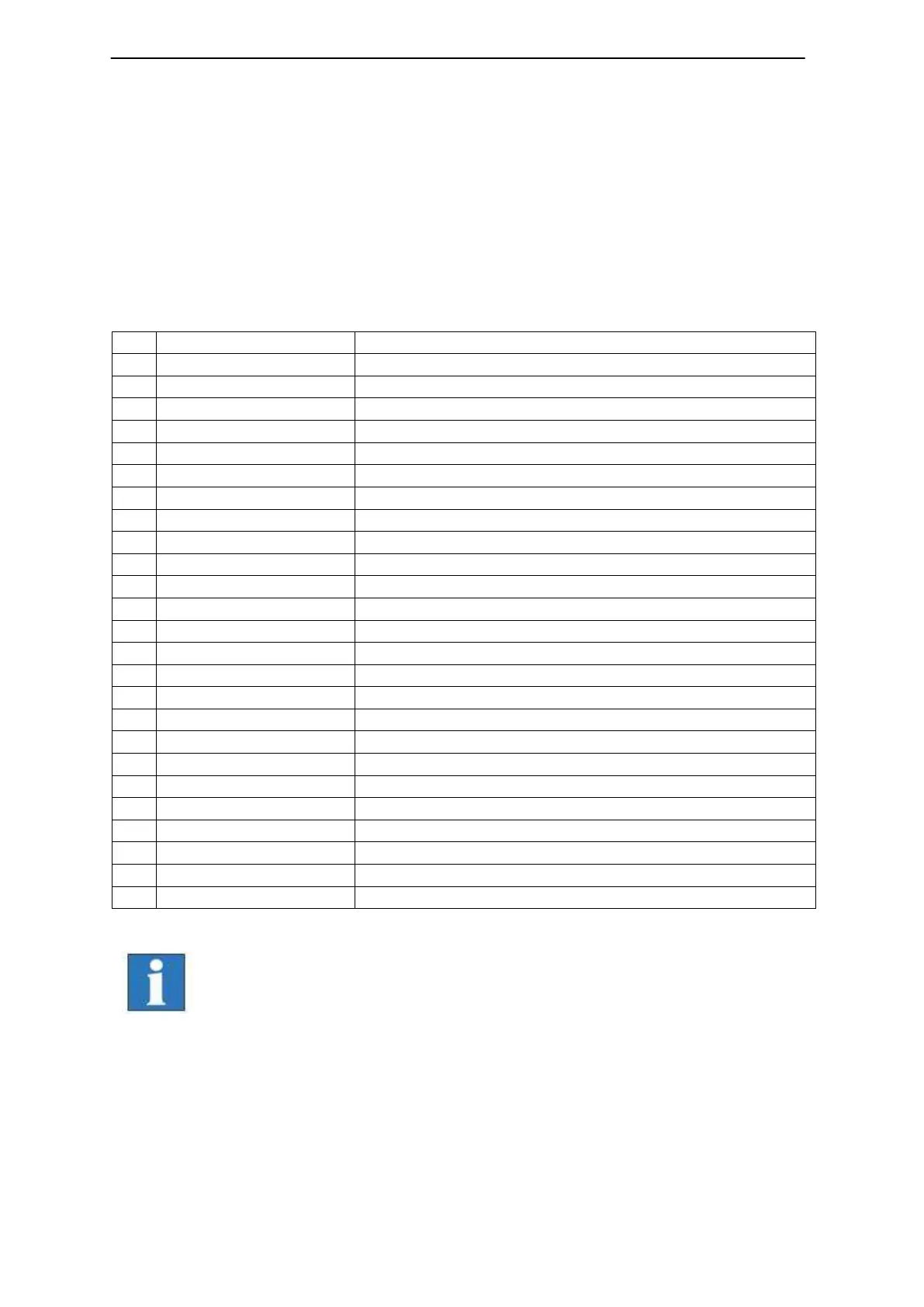
Emergency stop channel 1, 1.1
Emergency stop channel 1, 1.2
Emergency stop channel 2, 2.1
Emergency stop channel 2, 2.2
Input key switch test mode
Input key switch automatic mode
Input acknowledge button channel1
Input acknowledge button channel 2
Input START button (make contact)
Input STOP button (break contact)
The maximum length of the connection cable for the hand control
unit / CNC control panel should not exceed 5m.