iMC-B / iMC-V Operating Instruction
page - 13
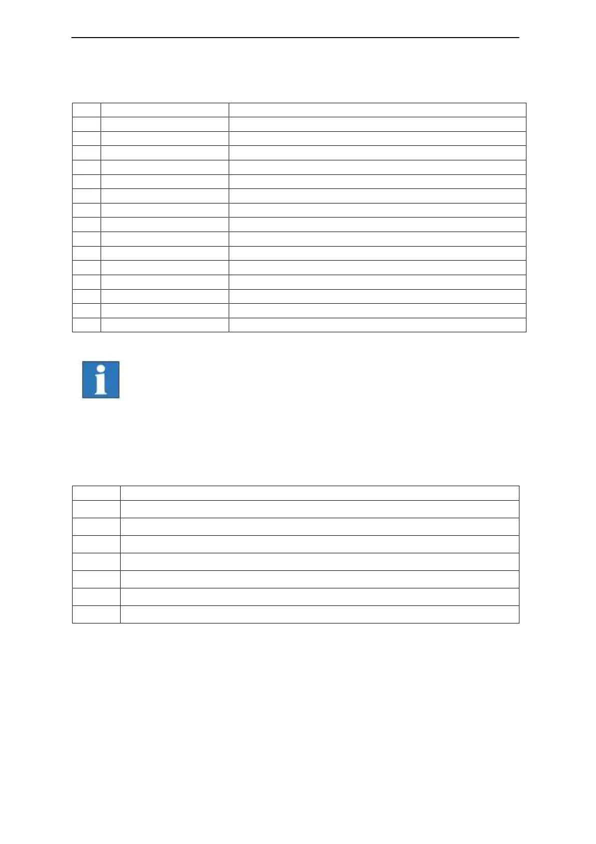
➂ External additional control console connector - 15-pin Sub-D (optional)
This connector is used if an additional isel control console is used.
Emergency stop channel 1, connector 1.1
Emergency stop channel 1, connector 1.2
Emergency stop channel 2, connector 2.1
Emergency stop channel 2, connector 2.1
Acknowledge channel 1, connector 1.1
Acknowledge channel 1, connector 1.2
Acknowledge channel 2, connector 2.1
Acknowledge channel 2, connector 2.2
Connector for cover button, connector 1.1
Connector for cover button, connector 1.2
Connector for cover button, connector 2.1 (option)
Connector for cover button, connector 2.1 (option)
The maximum length of the connection cable for the hand control
unit / CNC control panel should not exceed 5m.
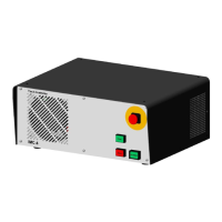
➃ Cover connector- 9-pin Sub-D- socket
Use this connector to integrate a cover or door control in the security circuit of the
controller.