iMC-B / iMC-V Operating Instruction
page - 14
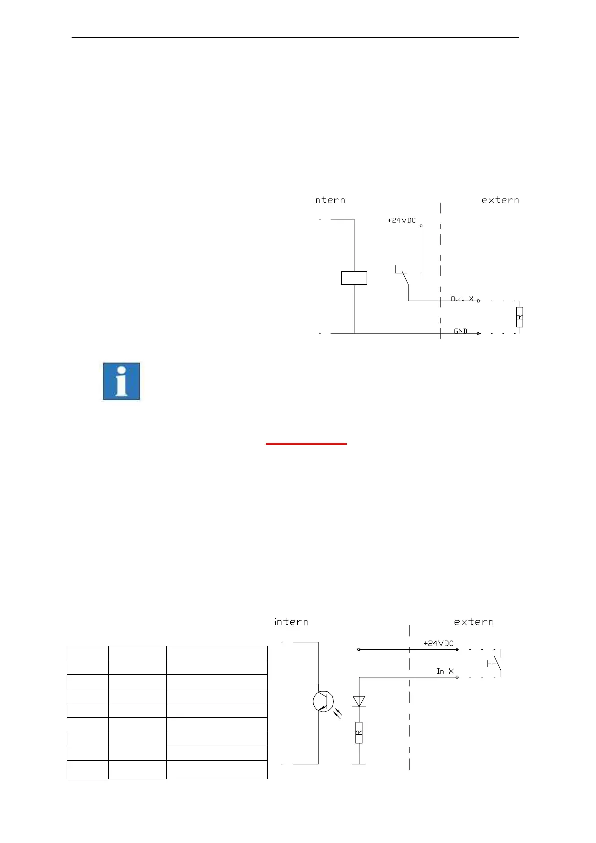
➄ Digital output port - 8-pin, left to right A2.1 – A2.8
The mounted I/O board has two digital output ports each with 8 digital switches. The
first output port (A1.1 – A1.8) is internal used for signalization. The second output
port can free configured by the user
Properties
- 8 x electronic outputs
- Imax < 350mA, 24VDC
- Thermic protection
- short circuit proof
Please note the default connection of the first output –port (A1.1
– A1.8) in the control software Remote / ProNC under the menu
entry „Signalization“.
These outputs are directly wired with the modules inside the
controller. You cannot longer use these outputs in the user
program!
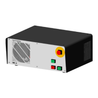
➅ Digital input port - 8-pin, left to right E1.1 – E1.8
The mounted I/O board has two digital input ports each with 8 digital inputs. The
second input port (E2.1 – E2.8) is internal used for signalization. The first input port
can free configured by the user.
Properties
- opt coupled inputs
- input current ca. 8mA