B
A
C
A
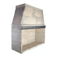
FRAMED OP'G.
MINIMUM
FRAMED OPENING
C
14
Rough Framing Dimensions
Corner Location Layout
Rough Framing Dimensions
Model Width Height Depth
A B C
Magnum
Model 28 38 1/2” 61 1/2” 29.5”
Model 36 46” 71” 29.5”
Model 42 52” 71” 29.5”
Model 48 56” 71” 29.5”
Isokern Standard
Model 36 46” 65” 26 3/4”
Model 42 52” 65” 26 3/4”
Model 46 56” 65” 26 3/4”
Notes:
1. “B” includes the 3” thick base plate. “B” is reduced by 3” if the base
plate is eliminated to create a “ush hearth”.
2. “Raised hearth” requires additional rough opening height at “B”
equal to the height of the raised hearth detail.
3. Rough framing dimension for width “A” allows for the required
1-1/2” clearance at the sides of the Fireplaces.
4. Rough framing dimension for depth “C” allows for the required
1-1/2” clearance at the back of the Fireplaces.
The following chart of dimensions is intended to aid in the positioning
of a replace in a corner condition where the DM chimney must turn 45°
degrees to align with overhead framing.
Magnum A B C D
Model 28 33 1/2” 18 1/4” 24” 65 1/2”
Model 36 43” 16 3/4” 32” 78 3/4”
Model 42 49” 26 1/2” 36” 83”
Model 48 53” 28 1/2” 39” 85 3/4”
Isokern Standard
Model 36 43” 49” 35” 72”
Model 42 49” 52” 37” 75”
Model 46 53” 54” 39” 79”
To turn ue 45°, rst set one offset block on the rebox so that
the chimney offsets 3” toward the back of the rebox. (Figure 6)
Set a DM outer casing onto this offset block so that the outer
casing is at 45° to the rebox and square to the overhead framing system.
Run the vertical DM chimney through the overhead framing.
More offset blocks can be used - if necessary to align with
overhead framing - before running the vertical DM chimney outer casing
and liner.
Note: Support the third offset down to footings and at each third offset
block thereafter (see pages 33 & 34).
FIGURE 5
FIGURE 6
 Loading...