PLUMBLINEPLUMBLINE
MEASURE
TRAVEL
DISTANCE
OVERHEAD
OBSTRUCTION
TRAVEL
DISTANCE
36
DM Chimney System: Offset Block (cont.)
When establishing the “far face” of the overhead
obstruction, be sure that the DM chimney blocks can run straight
to chimney termination without further overhead obstruction .
(Figure 59)
Be sure that there is sufcient space beyond the “far
face” of the overhead obstruction to accept the DM chimney’s
outer casing dimension of 21 1/2”. Support all offset sequences
down to bearing as discussed on previous pages.
Notes:
A) Always support the last offset block in a sequence
for full support of the DM chimney where it returns to vertical.
Support columns often carry the majority of the total load of the
vertical chimney that is set onto the last offset block.
B) The total chimney weight above the last offset
block will be the total weight of the vertical chimney plus any
additional allowable loads such as the Isokern brick ledge, its
related brick or stone veneers, and any crown caps, or other
chimney terminations.
C) Be sure the foundation under all support columns
is made of concrete or steel and designed to support the loads
applied to it.
D) Check with local codes and a structural engineer to
conrm loading and foundation requirements.
E) Maximum horizontal distance of offset is six feet
(6’) and represents twenty-four offset blocks in sequence.
F) By code the maximum angle of offset for a chimney
system is 30° off of vertical.
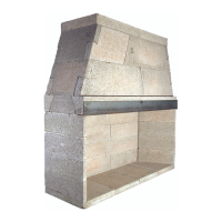
DM Brick Ledge:
The DM brick ledge is a 3” thick, 31-1/2” square, steel
reinforced, concrete and pumice slab (Figure 60).
The Brick ledge provides a 5” ledge at all four sides
of the outer casing block and is designed to support masonry
veneers to DM chimneys starting below the rafters and
continuing to termination. (Figure 61)
The component is cast with an octagonal hole in its
center so that the DM octagonal inner liner can pass through it.
The brick ledge has four 2-1/2” holes through it that
align with the hole in each of the four corners of the DM outer
casing block. These four holes are provided for reinforcement
of the chimney stack by the insertion of #4, minimum, steel
reinforcing rods and subsequent grouting. (Figure 60 & 61)
The brick ledge is intended for use in chimneys that
rise through the roof only where all four sides of the chimney
are bounded by the roof.
WARNING: To maintain structural performance the DM brick
ledge must not be cut or altered in any way.
FIGURE 58
FIGURE 59
31 1/2”
BRICK LEDGE
31 1/2”
3”
FIGURE 60
 Loading...