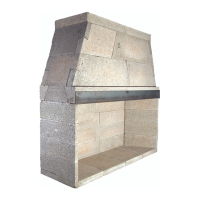
Flex Duct To Fireplace,
(All Parts Noncombustible)
Exterior
Wall
Exterior Air Vent
With Dress Plate
Typical Placement of
Gas or Electric Conduit
(See Detail Below)
Supply Air Ventilation
(If Required By Code)
CAUTION:
All access holes must be
grouted with mortar - after line
or conduit feed to seal any
gaps or cracks around line
feed conduits
Fire Brick Side
Gas or Electric
Conduit
NOTE: Fill Any Gaps
Around Conduit With Mortar
19
Access Modication
Through-Wall Accesses:
1. Combustion Air Inlet: Combustion air inlet kits though
not required by Earthcore may help improve replace
operation in homes tightly sealed and with other ventilating
appliances installed (Figures 20 & 21). Check local codes
for combustion air inlet requirements.
The following is a general representation of
a generic combustion air kit and not a requirement of
Earthcore Industries. Local building codes prevail and
should be checked before installation.
Generic replace combustion air kits typically
consist of a sliding stainless steel access door afxed to a
three inch (3”) or four inch (4”) diameter stainless steel sleeve
approximately twelve inches (12”) long. An exterior vent
with dress plate, weather hood and rodent prevention screen
of a maximum one-quarter inch (1/4”) wire mesh completes
the kit. (Figure 20)
The access door is tted into the nished re brick
lining at the interior sidewall of the rebox. The twelve inch
(12”) long sleeve can be introduced into the rebox side wall
by core drilling an appropriately sized hole at the selected
rebox location. Keep the top of the access hole no more than
six inches (6”) above the nished rebrick oor. The hole
size should allow for a one-quarter inch (1/4”) mortar joint
around the air access sleeve for heat expansion.
The sleeve passes through the rebox side wall and
must be connected to metal pipe (by others) - either exible
or rigid - that leads to the source for outside combustion air,
as directly as possible from the replaces (Few to no bends)
with a maximum length of sixty feet (60’).
WARNING: Do not use combustible duct material. Avoid
installing a combustion air inlet where the opening could be
blocked by snow, bushes or other obstacles. Air inlet must
terminate a minimum of three feet below the chimney cap
level. Air inlet ducts shall not terminate in attic spaces.
2. Gas Line Feed: For a replace having the provision for
installation of a gas pipe, the provision is intended only for
connection to a decorative gas appliance.
CAUTION: When using the decorative appliance, the
replace damper must be set in the fully open position.
Gas line for gas log sets used in the Isokern rebox can be
routed through the side wall of the rebox by drilling an
appropriately sized hole using a masonry drill bit (Figure 21).
3. Electrical Line Feed can be routed through the rebox
side walls by drilling an appropriately sized hole using a
masonry drill bit (Figure 21). Be sure to follow the gas log
Appliance Manufacturer’s explicit electrical line connection
instructions for vented masonry replace installations. Gas
line and electric line must be fed through separate access
holes. Be sure to ll any gaps around conduit with EC mortar.
(Figure 22)
FIGURE 20
FIGURE 21
FIGURE 22
 Loading...