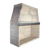
FIRST COURSE
SIDEWALL
BASE PLATE
EC
MORTAR
EC
MORTAR
16
Assembly Instructions - (cont.)
3. Earthcore mortar can be troweled over the face of a joint
where it has squeezed out while setting components. It is not
intended that the exposed faces of the Isokern components be
completely covered with mortar.
Installation:
Step 1: Set the base plate in a full bed of Earthcore Mortar at
on a proper concrete support foundation. (Figure 10). Do not
set the base plate so that it is in span. Level the base plate by
oating it in a bed of Earthcore Mortar to full bearing against
the underlying noncombustible support surface.
Notes: If the design preference is for a “ush hearth”
(replace oor ush with the room’s oor), the base plate
can be omitted from the assembly and the rebox walls built
directly on the concrete support slab. The re brick oor of the
rebox is then set directly to the concrete support slab. This
makes the replace nished re brick oor approximately
one and one-half inches (1-1/2”) above the top of the concrete
support slab. (Figure 11)
If the design preference is for a raised hearth (oor
of the replace elevated above the room’s oor), then the base
plate can be set on a noncombustible platform that is built up
to the desired raised hearth height on the concrete support
slab. (Figure 12)
When calculating raised hearth height be sure to
allow for the three inch (3”) thick base plate plus the one and
one half inch (1-1/2”) thick re brick oor in addition to the
height of the platform.
Whether a ush hearth is preferred or a raised hearth,
the combustible oor on front of the replace must be covered
with a noncombustible hearth extension set tight against the
replace front and extending at least 20 inches out from the
nished replace and at least 12 inches beyond the nished
sides of the replace opening.
For all “raised hearth” construction where concrete
blocks are used to create the raised platform, it is necessary
to use the base plate. Be sure to mortar the concrete block
platform together. CMU used for base plate support should be
rated ASTM 90.
Step 2: Set the rst course of the rebox back wall and side
walls into place.
It may be convenient to dry set the rst course of
side wall and back wall into place on the Isokern base plate
and then to trace their position on the base plate with a pencil.
After outlining the dry set pieces, remove them and
apply Earthcore Mortar to the areas traced on the base plate
where the side walls and back wall are to sit. By doing this,
the rst layer of Wall components can be set directly into
mortar already applied to the proper areas on the base plate.
Be sure to put Earthcore Mortar on the contact surfaces of the
vertical joints where the side wall and back wall components
connect. (Figure 13)
FIGURE 10
FIGURE 11
FIGURE 12
FIGURE 13
 Loading...