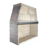
TWO COURSES
BACKWALL
EC
MORTAR
FIRST DAMPER
SUPPORT IN
PLACE
CAST IRON
DAMPER
FRONT DAMPER
SUPPORT
17
Assembly Instructions - (cont.)
Note: At all component placement, be sure to mortar all
component contact surfaces with Earthcore Mortar. Check for
complete sealing of each contact joint while assembly progresses.
Step 3: Continue assembly of the consecutive courses of the
rebox side wall and back wall. (Three courses for the Isokern
Standard Series, Four courses for the Magnum Series). Apply
mortar to the top of each layer of wall components, set the next
course above into place. Be sure to mortar all vertical joints of the
side wall to back wall connection when setting each component
to its mate. (Figure 14)
Look for some mortar to squeeze out along the joints of
all contact surfaces as a sign that the joint is thoroughly sealed
with the approved mortar.
Step 4: When all of the rebox wall components are set, check
the top surface of the rebox for level. If necessary, adjust the top
surface of the box assembly for level by inserting a shim between
the lowest wall component and the top surface of the base plate.
(Figure 9)
Any gap created under the wall components during the
Shim leveling process must be lled with mortar to full bearing
against the base plate.
Step 5: Make sure that the rebox assembly has been set level
and square. Adjust as required while the mortar is still wet.
Make a nal inspection of all contact joints in the
rebox assembly to be sure they are properly sealed. Fill any and
all gaps in the assembly, as necessary, with the approved mortar.
Step 6: The replaces come with an eight inch (8”) thick damper
beam assembly, a four piece component group that is to be
assembled on top of the rebox sidewalls.
The damper beam assembly consists of two long lintel
pieces and two short damper beam side pieces.
The damper side pieces are designed to sit on the rebox
side wall between the front lintel and the back lintel. Each of the
damper side pieces is designed specically for its own side of the
unit. When properly set, each damper side piece ts ush with
the outside face of the rebox sidewall so that its interior bottom
edge aligns with the interior angle of the rebox side wall that it
sits on. (Figure 15)
The two long lintels are identical in shape, size and in
length, equal to the width of the replace model that they serve.
Properly placed, one lintel is to sit on top of the rebox back wall
and ush with it; the other lintel sits ush with the front of the
rebox, spanning the rebox opening. These components both sit
on their narrow base so that their beveled face points down and
into the rebox interior. (Figure 16)
Be sure to mortar all damper beam components to the
top surfaces of the rebox.
Mortar the contact surfaces of each damper side
component where it meets the front and back damper beam lintel
components.
FIGURE 14
FIGURE 15
FIGURE 16
 Loading...