Power Supply Function
• U
n
: Peak voltage
Parameter
Type of system
Minimum test
requirements
12V 24V
U
n
a
(V)
79≤U
n
≤101 151≤U
n
≤202
10 pulses at 1 min intervals
Ri
a
(Ω)
0.5≤Ri≤4 1≤Ri≤8
t
d
(ms)
40≤t
d
≤400 100≤t
d
≤350
t
r
(ms)
– –
a
If not otherwise agreed, use the upper voltage level with the upper value for
internal resistance or use the lower voltage level with the lower value for in-
ternal resistance.
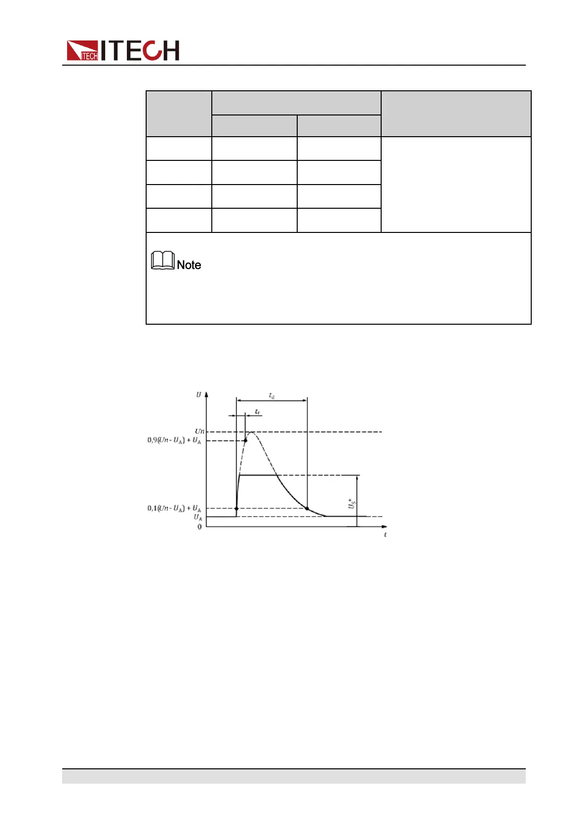
The pulse shape and parameters for an alternator with centralized load dump
suppression (Test B) are given in follow.
• t: Time
• U: Voltage
• t
d
: Duration of pulse
• t
r
: Rising Slope
• U
A
: The supply voltage of the generator in operation: U
A
=14V in the 12V sys-
tem, U
A
=28V in the 24V system. (see ISO 16750-1)
• U
n
: Peak voltage
• U
S
*: Supply voltage with load dump suppression (i.e. clamping voltage)
U
S
* = (Us − 4.28) × Un ÷ 80
Us is the setting item in the menu.
Copyright © Itech Electronic Co., Ltd.
96
 Loading...

