Power Supply Function
1. Press the composite keys [Shift]+[I-set] (Function) on the front panel to en-
ter the function menu.
2. Use the knob or press the Up/Down key to select 3.Road-Vehicles = Off
and press [Enter].
3. Press the Left/Right key to select LV123, and press [Enter] to confirm.
4. Press the Left/Right key to select Curve→Edit→unlimited→HV_1, and
press [Enter] to confirm.
5. Set start voltage = 50V, start time = 0.1S, end time = 0.1S and count = 1.
6. Set Save To File = 1, and press [Enter] to confirm.
7. Select Open→Recall File in the main interface of LV123. Set to 1, and press
[Enter] to confirm.
8. Select RUN in the main interface of LV123, and press [Enter] to confirm.
At this time, the information of the recalled waveform is displayed in the low-
er right corner of the VFD screen: R1/HV_1/00001, which is represented as
the interval type of the waveform, the type of the regulation, and how many
times the waveform has been executed cyclically.
9. Press [On/Off] on the front panel to turn on the output.
10.According to the selected trigger method (same as the trigger method of the
LIST function), for example, press [Shift]+[On/Off](Trigger) to trigger the
output of the waveform.
4.6.3.6 LV124
The built-in curves LV124 can meet general requirements, test conditions and
tests of electrical and electronic components in motor vehicles up to 3.5 t. Re-
lated parameters are as below:
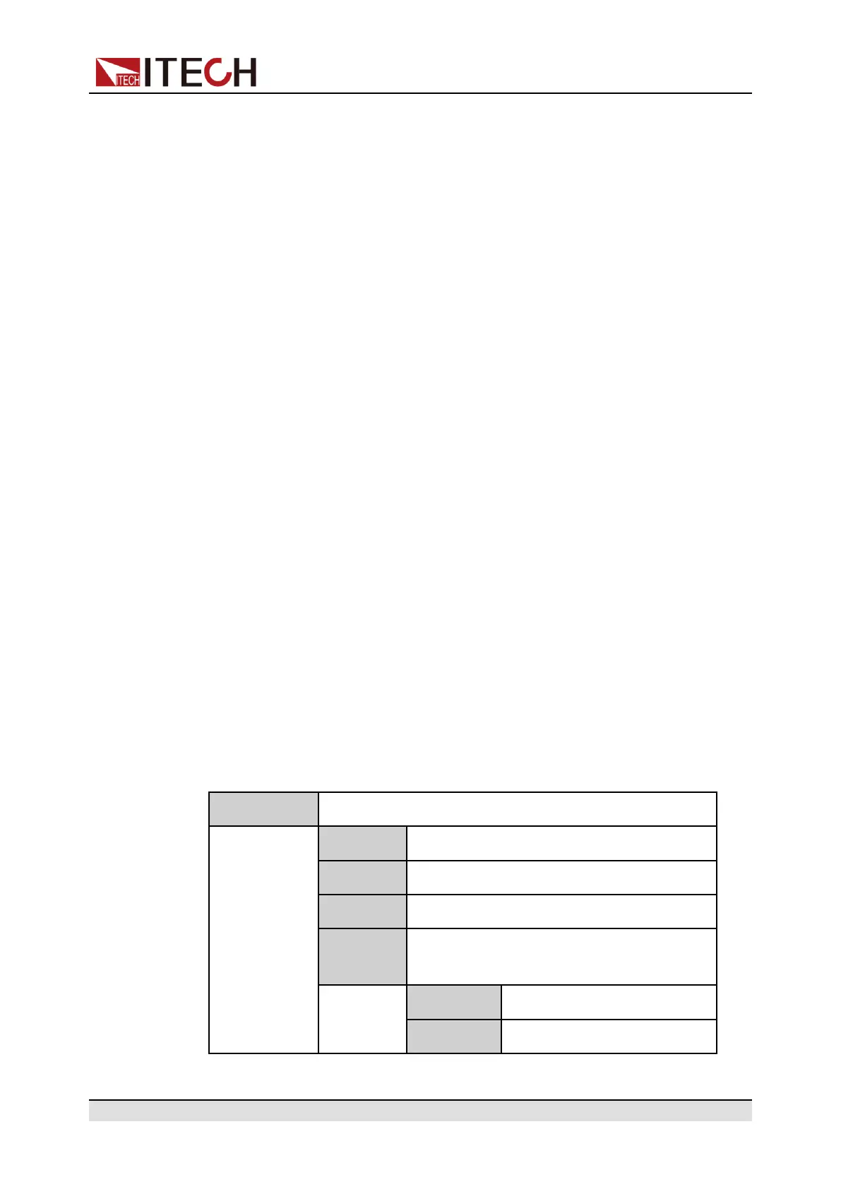
LV124 LV124 waveform protocol
E-02 Transient overvoltage test waveform
E-04 Jump start test waveform
E-05 Load dump test waveform
E-07 Slow decrease and increase of the supply
voltage test waveform
Ubmax Start voltage
Ubmin Holding voltage
Copyright © Itech Electronic Co., Ltd.
98