Basic Operation
1 100
Maximum low level input
voltage
0.8V
Typical high level output
voltage
5V
Typical low level current 0V 0.5mA
Minimum high level input
voltage
1.6V
Level rise slope 10us
Level fall slope 2us
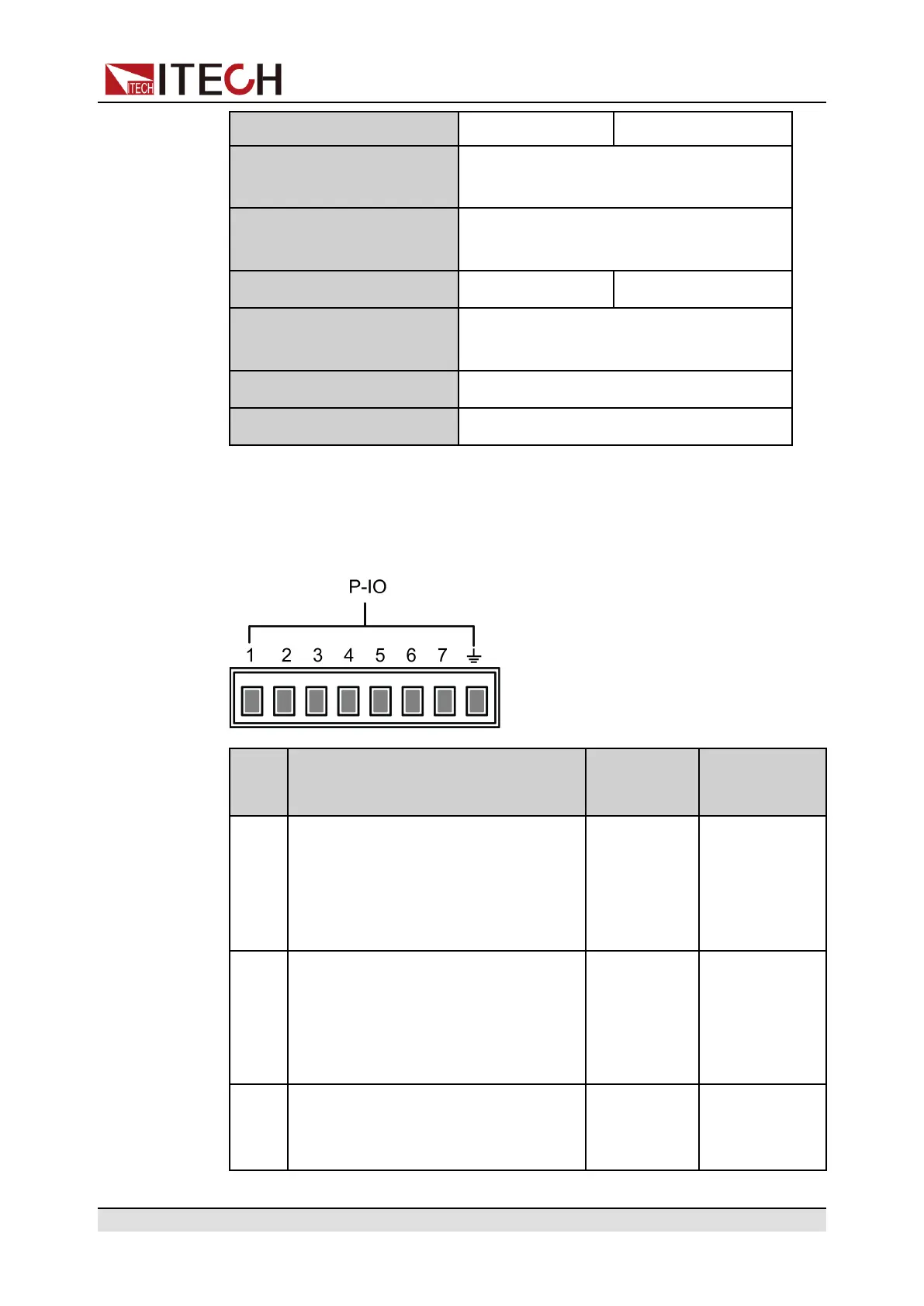
Pins Introduction
The appearance of the terminals are shown below.
Pin Description Properties
(Default
function)
Properties
(General I/O
function)
1 Corresponds to the function set in the
System→Digital Port→IO–1. Ps-
Clear, Not-Invert menu item. For pa-
rameter introduction, see 5.11.1 IO–
1. Ps-Clear, Not-Invert.
Pulse signal Level or PWM
signal
2 Corresponds to the function set in the
System→Digital Port→IO–2. Ps,
Not-Invert menu item. For parameter
introduction, see 5.11.2 IO–2. Ps,
Not-Invert.
Level signal Level or PWM
signal
3 Corresponds to the function set in the
System→Digital Port→IO–3. Off-
Status, Not-Invert menu item. For
Level signal Level or PWM
signal
Copyright © Itech Electronic Co., Ltd.
127
 Loading...

