System-Related Functions
Copyright ©ITECH Electronic Co., Ltd. 69
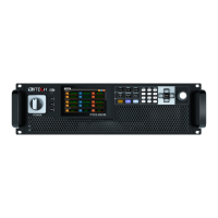
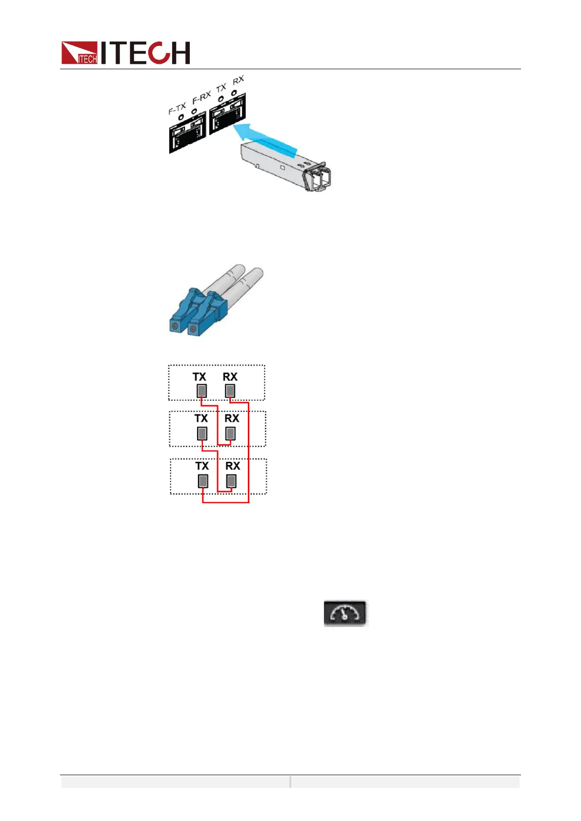
b) Insert the plug of the fiber optic cable into the fiber optic module and hear a
click sound to indicate that it is inserted in place. The fiber optic cable
connection schematic is as follows.
Set the Parallel Mode
1. Turn on the main switch of the AC distribution box and power on each of the
three units.
2. Set three units in parallel mode with one master and two slaves.
3. Press the composite keys [Shift]+ (System) on the front panel to
enter the system menu.
4. Select General menu.
5. Set the Parallel Mode, set them to one master unit and two slave units. In
each group, one instrument must be the master unit and all other instruments
connected in parallel are slave units. All features are set up from the master
unit.
⚫ Single: Default value, indicates that the instrument is in single mode.
⚫ Master: Indicates that the single unit is set to master in parallel mode.
Numbers: total number of units in the parallel relationship, when the