EasyManuals Logo
Home>ITech>AC Power Distribution>IT7800 Series

ITech IT7800 Series User Manual

ITech IT7800 Series
118 pages
To Next Page IconTo Next Page
To Previous Page IconTo Previous Page
Page #73 background imageLoading...
Page #73 background image
System-Related Functions
Copyright ©ITECH Electronic Co., Ltd. 71
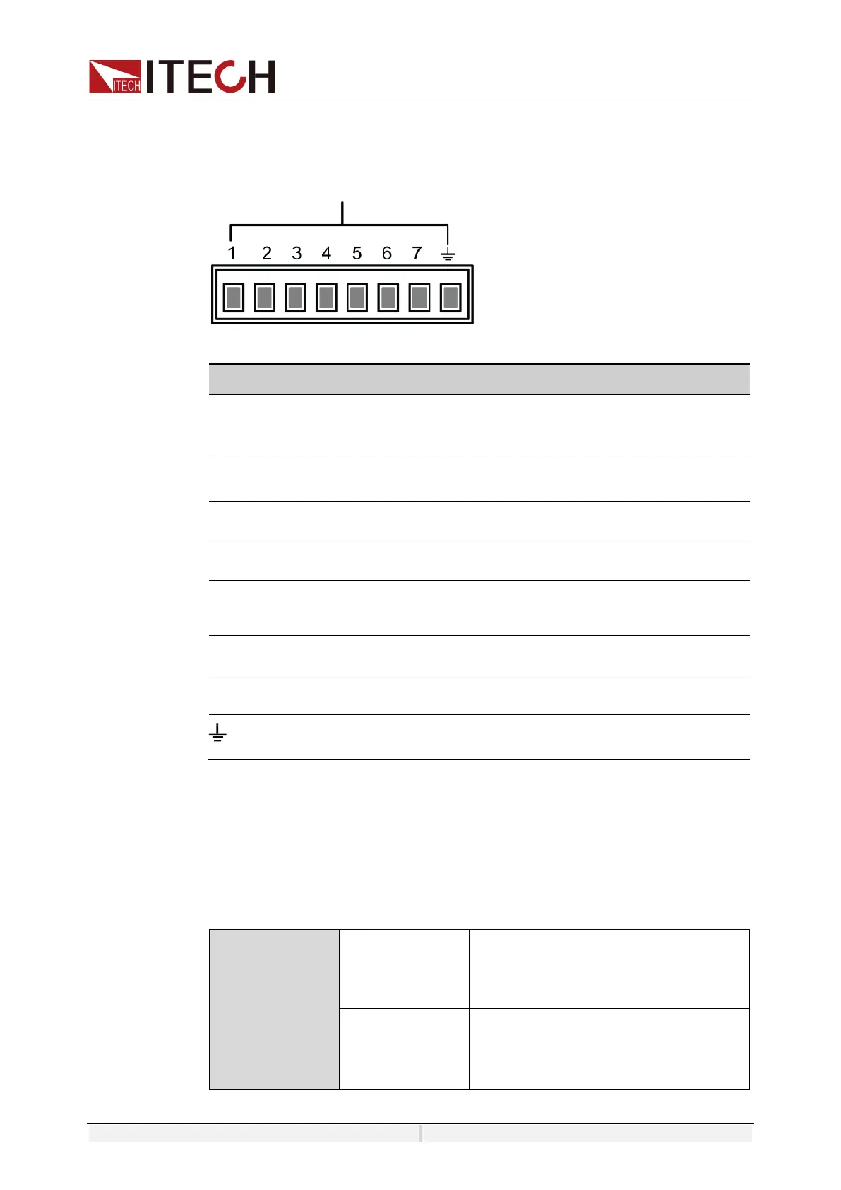
Pins Introduction
Different I/O implements different functions. The detailed functions description
are shown in the figure below:
Digital-IO
Pin
Type
Description
Properties
Digital IO-1
Input/Output
Inhibit, Turn off the output
under emergency status
Level signal
Digital IO-2
Input/Output
Ps-clear, Clear the protection
state
Pulse signal
Digital IO-3
Input/Output
PS, Protection state indicator
Level signal
Digital IO-4
Input/Output
Sync, synchronous control
Pulse signal
Digital IO-5
Input/Output
OnOff-status, OnOff-status
indicator
Level signal
Digital IO-6
Input/Output
Trigger1
Pulse signal
Digital IO-7
Input/Output
Trigger2
Pulse signal
Ground terminal, that is, the negative terminal corresponding
to each of the above 7 pins.
General Digital I/O Function
Signal definition
Digital I/O functions involve input and output levels and pulse signals.The input
signal is the control signal provided externally to IT7800, the output signal is the
level signal provided externally by IT7800, and the pulse signal is the edge
signal switched between high and low levels.
Input signal
High level signal
Typical: 5V
Range: 1.6V-15V
Current: ≤100mA
Low level signal
Typical: 0V
Range: -5V-0.8V
Current: ≤100mA

Table of Contents

Questions and Answers:

Question and Answer IconNeed help?

Do you have a question about the ITech IT7800 Series and is the answer not in the manual?

ITech IT7800 Series Specifications

General IconGeneral
BrandITech
ModelIT7800 Series
CategoryAC Power Distribution
LanguageEnglish

Related product manuals