Description and installation
The following description corresponds to the labels in Figure 3-1.
1. Power Supply Connector Connects the EAR 1000/2000 to the external
power supply
2. 1/2 RJ-11 Sockets Connects the EAR 1000/2000 to PBX extensions
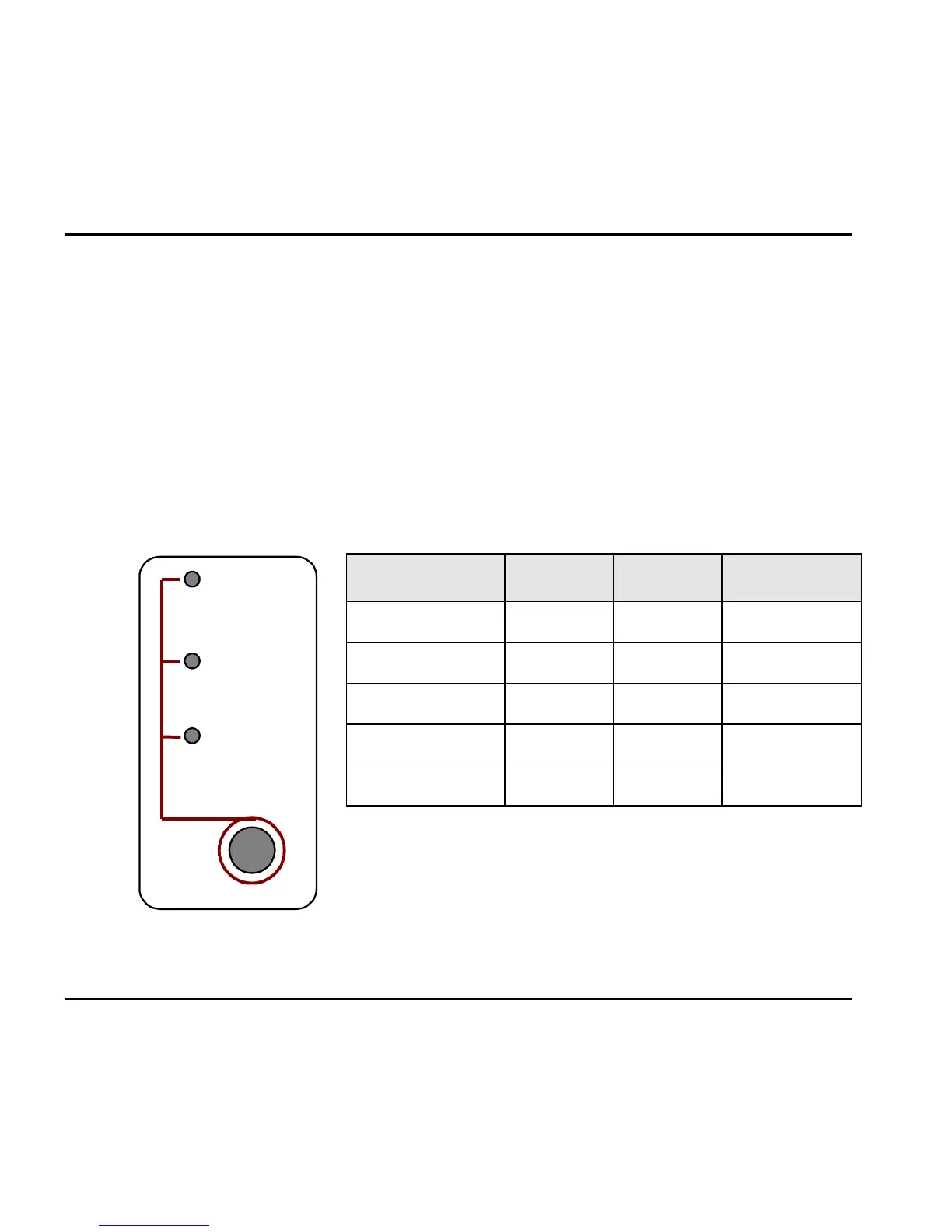
3.1.2 Front Panel
The following figure and table describe the function of the three LEDS on the front
panel.
Set
- Day
- Night
- Holiday
Figure 3-2. LEDs on
the Front Panel
STATUS DAY NIGHT HOLIDAY
Day Mode On Off Off
Night Mode Off On Off
Holiday Mode Off Off On
System Error
1
Off Flashing Off
System Error
1
Flashing Flashing Flashing
1
Please contact your local dealer.
3-2 EAR 1000/2000 Installation and Programming Manual