Do you have a question about the ITT GOULDS PUMPS 3311 and is the answer not in the manual?
This document provides installation, operation, and maintenance instructions for Goulds Pumps, model 3311. It covers various aspects of the pump, including safety, application, system layout, unpacking, handling, storage, installation, starting, stopping, maintenance, disassembly, assembly, and troubleshooting.
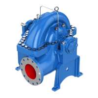
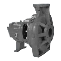
The Goulds Pumps model 3311 is a high-pressure pump, specifically a horizontal multi-stage ring-section type centrifugal pump. It is designed for various industrial applications, including municipal water supply, pumping stations, treatment plants, booster units, water treatment, filtration, reverse osmosis, general water supply, cold water, boiler feed installations, hot water, pumping of organic and inorganic solutions, high-pressure gas washing, power water generation plants, purifying and cleaning plants, desalination plants, power supply, and small and medium-sized thermal stations, waste incineration installations. The pump's design incorporates a hydraulic balancing device to manage axial thrust.
The pump's design and working principle adhere to technical requirements according to DIN ISO 5199 / EN 25199. The pump casings are held together by external tie bolts and sealed against the atmosphere by O-rings. The axial thrust is balanced by a hydraulic balancing device consisting of a disc/drum combination. An additional lift-off device is available and intended for special applications. The balancing liquid flows back through an external line to the suction casing.
The suction nozzle can be axial or radial. In the case of radial suction nozzle orientation, the suction casing pump feet assembly allows adaptation to the installation requirements by rotating the casing. Bearings are oil-lubricated anti-friction bearings on the discharge side, and suction side sleeve bearings are lubricated by the liquid handled or oil-lubricated anti-friction bearings. The shaft seal can be a packed stuffing box or a mechanical seal according to DIN 24960. The drive is specified in the data sheet.
The minimum flow rate for operation with the discharge side shut-off valve closed is provided in a table, with specific percentages of QBEP (Best Efficiency Point) for different pump sizes (2x3-7, 2.5x4-8, 4x5-11) and temperatures (t ≤ 140 °C or lower, t > 140 °C).
The pump's operation is limited to the application and operating conditions stated in the manufacturer's data sheet. Using the pump for wrong applications or outside its characteristic curve can increase risk to personnel safety and the environment.
Proper system layout is crucial for optimal performance. Pipework should be designed to minimize pressure losses. Suction lines should slope gradually downwards towards the pump, and shut-off valves must be installed in the suction and discharge lines. Air-relief valves and drain valves should be installed in the suction and discharge lines. Eccentric reducers are recommended in the suction line to prevent air pockets. A foot valve with a strainer should be used in the suction line, and the suction opening should be submerged to prevent air entry. An equalizing pipe must be installed connecting the vent connection at the suction casing or the highest point of the suction line to a point above the maximum liquid level in the suction tank.
For flow control, a shut-off valve is installed as close to the pump nozzle as possible. A non-return valve is installed between the pump nozzle and the shut-off valve to protect the pump against reverse rotation and also the pump and the foot valve against water hammer that may occur in the event of sudden shut-down. A bypass non-return valve or a shut-off valve must be installed in the minimum flow line for repair or overhaul work.
Electrical connections for the driving motor must comply with relevant rules and requirements. Pressure monitoring points are recommended upstream and downstream from the pump.
Regular maintenance and inspection are essential for safe and reliable operation.
Oil-lubricated anti-friction bearings on the drive side and sleeve bearings on the suction side require regular oil checks. The oil level should be visible in the screw-in elbow. New oil should be filled until it becomes visible in the screw-in elbow. Oil should be changed after 200 operating hours initially, and then every six months or every 50 operating hours if the temperature is below 50 °C, or every six months if the temperature is above 50 °C. The document provides a table for bearing temperature and ambient temperature, specifying lubricating oil classes (CL 68, CL 46, CL 22) based on n ≥ 1500 rpm and n < 1500 rpm. Kinematic viscosity, neutralization number, ash content, water content, and oil consumption are also specified.
Generally, no maintenance is required on mechanical seals unless there is visible leakage. In case of heavy leakage, the mechanical seal should be checked.
A packed stuffing box may experience leakage. The packing and shaft wearing sleeve should be checked for scores. The stuffing box leakage must be adjusted until start-up (refer to 7 Starting & Stopping Procedures on page 28).
Only pre-compressed packing rings are permissible. The packing ring should not be laterally bent open and pushed on the shaft wearing sleeve. The packing ring should slide into the packing chamber using the stuffing box gland. The other packing rings should be installed in the same manner, with the gaps 180° apart. The gland should be tightened finger-tight. The gland should not be tightened at a slant. The pump rotating assembly must be free to rotate by hand.
Iron pumps are usually preserved. To remove the preservative coating, the pump should be filled and drained several times using appropriate agents (e.g., solvent naphtha, diesel oil, or an alkaline detergent). Flush with water if necessary. The pump must be installed and put into operation immediately afterward. If the pump has been supplied preserved and is to be stored, a new preservative coating should be applied after six months.
Detailed instructions are provided for dismantling various components, including the bearings (sleeve bearing, anti-friction bearing), shaft seal (stuffing box packing, mechanical seal), balancing device, and hydraulic unit. Specific steps are outlined for removing covers, circlips, bushes, sleeves, keys, bolts, nuts, and other parts.
Before disassembly, the pump must be purged of any residual liquid. The environment must be free of explosive, toxic, crystalline, or acid liquids. The workplace for disassembly or assembly must be clean.
A comprehensive table lists common troubles, their causes, and remedial actions. This includes issues like insufficient liquid delivered, insufficient suction performance, pump leakage, temperature increase in the pump, increase in bearing temperature, unsteady running of the pump, excessive noise, and motor circuit breaker switches off.
A detailed parts list with Gould's Item #, Part number DIN, and Denomination is provided for various components of the pump.
Instructions for ordering parts are provided, including contact information for Goulds Pumps and emergency service.
| Brand | ITT |
|---|---|
| Model | GOULDS PUMPS 3311 |
| Category | Water Pump |
| Language | English |