Do you have a question about the ITT Goulds Pumps CV 3196 i-FRAME and is the answer not in the manual?
| Model | CV 3196 i-FRAME |
|---|---|
| Category | Water Pump |
| Manufacturer | ITT Goulds Pumps |
| Series | 3196 |
| Frame | i-FRAME |
| Connection Type | Flanged |
| Shaft Orientation | Horizontal |
| Type | Centrifugal |
| Maximum Head | 730 ft (223 m) |
| Materials | Ductile Iron, 316 Stainless Steel, Alloy 20, CD4MCu |
| Seal Type | Mechanical Seal |
Purpose of the manual, how to request additional information, and important notices.
Details hazard levels, symbols, user, environmental, and Ex-approved product safety.
Details product compliance with regular standards (CSA, UL) and explosion-proofing approvals.
Outlines warranty coverage, limitations, and procedures for making a warranty claim.
Special care, intended use, and ATEX conformance guidelines for explosive environments.
Steps for inspecting the package and unit upon delivery for damage or missing items.
Guidelines for safe transport, handling, and proper lifting methods for the pump.
Requirements for pump storage based on duration and frostproofing considerations.
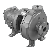
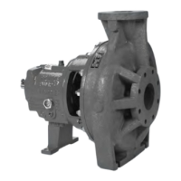
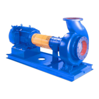
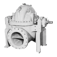
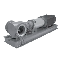
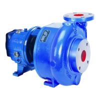
General description of the CV 3196 pump, its design, and media handling capabilities.
Description of the i-ALERT®2 monitor for measuring vibration and temperature.
Details nameplate information for ordering, identification, and types (pump, bearing, ATEX).
Precautions and guidelines for pump location and foundation requirements.
Procedures for mounting baseplates using shims, jackscrews, springs, or stilts.
Instructions for mounting and installing the pump, driver, and coupling assembly.
Critical procedures for aligning pump and driver for optimal performance and longevity.
Procedures and required equipment for grouting the baseplate to the foundation.
Checklists for general, suction, and discharge piping to ensure proper installation.
Essential warnings and precautions before initiating pump startup procedures.
Checks for correct rotation direction and impeller clearance for efficient operation.
Methods for setting impeller clearance using dial indicator or feeler gauge.
Steps for coupling the pump and driver, including guard installation and bearing lubrication.
Description of various shaft seal options and their connection requirements.
Instructions for installing the shaft guard for safety purposes.
Methods for priming the pump before startup, depending on suction supply position.
Precautions and steps for safely starting the pump after preparation.
Procedure for activating the i-ALERT® Health Monitor when the pump is running.
Procedure for safely shutting down the pump.
Details routine, three-month, and annual maintenance inspection schedules and tasks.
Procedures for bearing maintenance, lubrication requirements, and acceptable oils/greases.
Maintenance procedures for mechanical seals and packed stuffing boxes.
Step-by-step instructions for disassembling the pump, including precautions and tools.
Guidelines and checks for pump parts before reassembly, including replacement criteria.
Detailed steps for reassembling the pump, including bearings, seals, and frame.
Solutions for common pump operational issues like no delivery, low flow, noise, or vibration.
Troubleshooting steps for issues preventing proper horizontal alignment.
Troubleshooting common issues found during pump assembly, like shaft end play or runout.
Troubleshooting steps for the i-ALERT®2 monitor, including LED indicators and baseline issues.
Detailed list of pump parts, quantities, materials, and material-code references.
Official certificates for CSA, ATEX, IECEx, and Chinese conformity for explosion-proof equipment.
Instructions on how to obtain any other relevant documentation or manuals from ITT.
Contact details for ITT regional offices worldwide for support and inquiries.