M
Mason SalazarAug 5, 2025
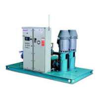
What to do if ITT Water Pump motor does not start?
- DdaughertyjermaineAug 5, 2025
If the motor of your ITT Water Pump isn't starting, here are a few things to check: * Ensure the power supply is properly connected. * Replace the fuse if it has blown. * Reset the panel’s automatic switch. * The motor may be defective, requiring repair or replacement.