RESCUE GUIDE ‒ Technical information
TECHNICAL INFORMATION
CNG / CNG-PETROL VEHICLES (NATURAL POWER)
11
– Printed 692.68.340 – 1st Ed. 04/2015
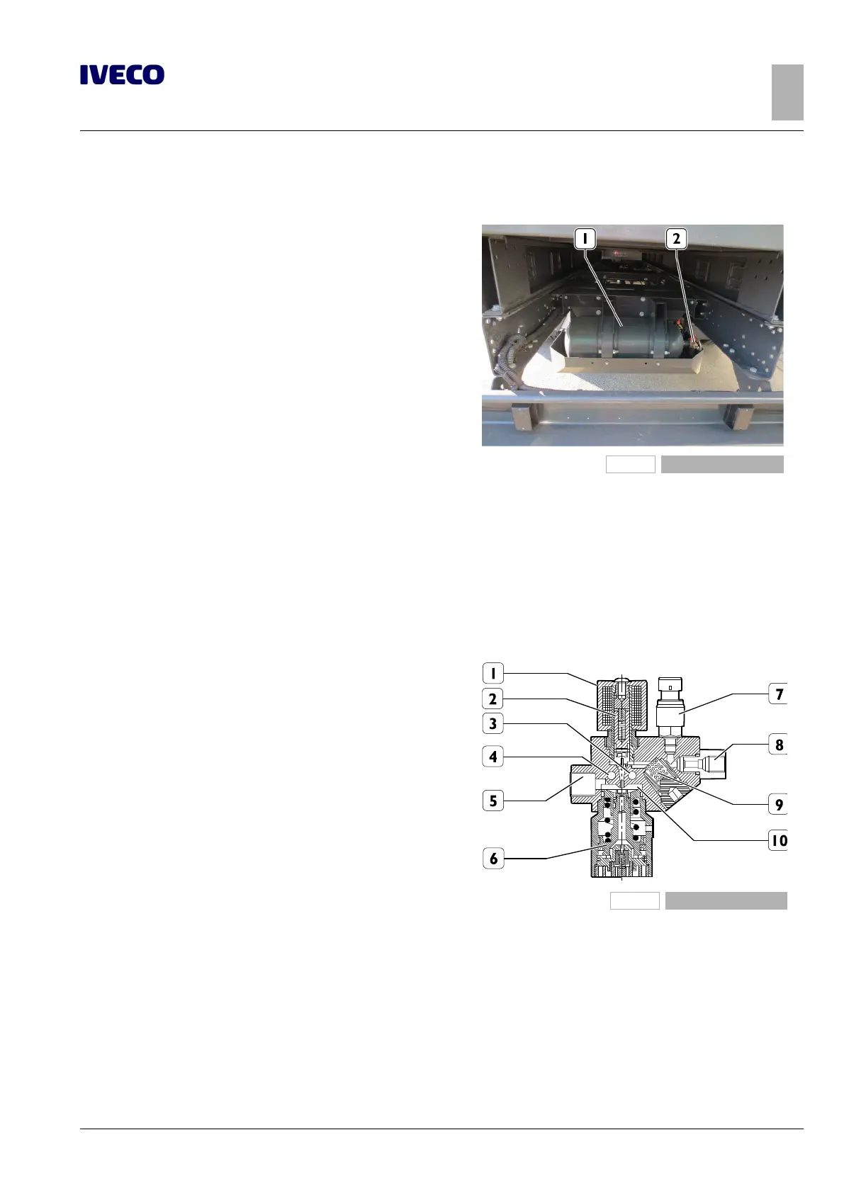
Cylinders description
Solenoid valve on cylinder
226155
Figure 12
1 Cylinder 2 Solenoid valve
The CNG, compressed at a pressure of 200 bar, is stored in some cylinders, positioned in the chassis frame and protected by spe-
cial sheet metal guards.
The cylinders, connected together in series, are filled via a filling valve equipped with a check valve.
A second check valve is included in the solenoid valve fitted on the first cylinder connected to the filling union.
The function of the check valves is to prevent the gas escaping outwards and the dispenser being removed from the filling valve
after refilling or a pipe bursting.
Pressure reducer description
138645
Figure 13
1 Solenoid valve
2 Valve mobile equip-
ment
3 Cooling water duct
4 Cooling water duct
5 Low pressure CNG
outlet
6 Reducer valve mobile
equipment
7 CNG pressure sensor
8 High pressure CNG
inlet
9 Filter
10 Discharge chamber
The pressure reducer decreases the CNG pressure from the value
in the cylinders to the electric injector supply value (6 ± 1 bar), in all
engine operating conditions.
The pressure reduction takes place in a single stage in which the
pressure is reduced from 200 to 6 bar
Since the CNG drops sharply in temperature because it expands due
to the jump in pressure, the engine cooling circuit has a branch that
allows the engine coolant to heat the pressure reducer assembly so
as to avoid any trouble due to the change in temperature, such as the
formation of condensation or even ice that could block the pressure
reducer.
It is equipped with a CNG shut-off solenoid valve and a CNG pres-
sure sensor.

 Loading...