Figure 26
Figure 27
Figure 28
Figure 29
Figure 30
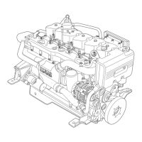
- From the front side disassemble the engine oil filter
supports (1) including the oil temperature transmitters
(2), the pressure sensor (5), the seal (4) and t he filter clog
sensor (3).
- Remove the remaining diesel pipe from the LPP to the
filter mounting (the two components have already been
removed previously)
- Remove the electro—injectors. Using the wrench (2),
unscrew the screw (1) of the fixing bracket.
- Fit the tool 99368505 (1) and the wrench for extracting
the electro—injector.
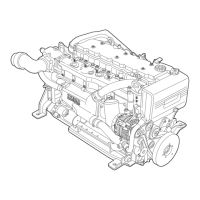
- Unscrew the fixin g screws (1) and remove the t appet
cover (2). Repeat this operation for all the covers.
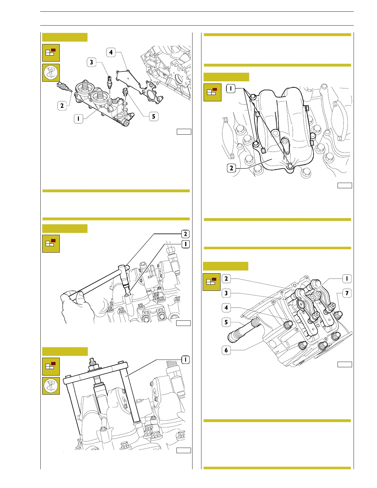
- Remove the rocker arms (2) from the support (1), taking
out the circlips and seals on both sides of the support.
Extract the rods (3) from their seat on the heads and the
jumpers (4).
- Unscrew the fixing screw s (7) and remove the head (6).
Remove the cases (5) protectin g the valves.
Always chan ge the O—ring in t he assembly phase.
Lubricate the O-rings with vaseline before
installating
82216
82220
82218
82217
82219
NOTE
If necessary, replace the worn parts. Always change
the seals in the assembly phase.
NOTE
NOTE
Note down the position of the tappet covers in
relation to the heads so as to fit them in the
positions they had with th e first assembly.
The screws (7) fixing the head on the crankcase
have different sizes:
M15x170
M15x185
Mark them so as to facilitate the assembly phase.
NOTE
SECTION 3 - INDUSTRIAL APPLICATION
19
VECTOR 8 ENGINES
Print P2D32V001E Base - April 2006