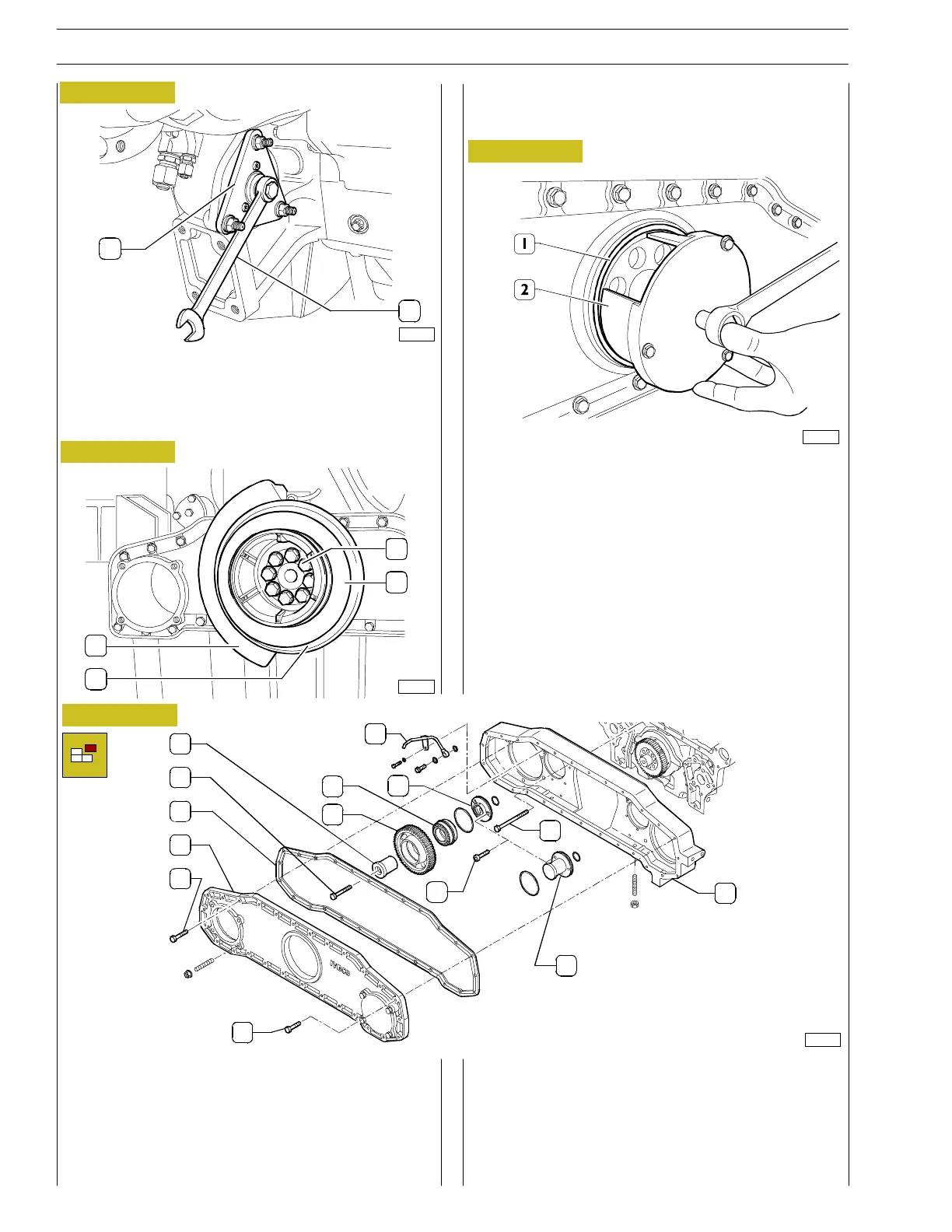
- Undo the M8 bolts (1) and remove the cover (2) for the
gear casing. Remove the gasket (3).
- Remove the duct (12).
- Unscrew th e screw (4), remove the shaft (5) and the
gear (6) with the bearing (7).
- Remove t he oil seal (1) using the tool 99368514 (2).
- Rotate the engine and remove the oil sump.
- Remove the engine lubricating oil pump with the suction
cup.
- Undo the bolt (10) securing the gear casing (11) to the
cylinder block/crank case; after having removed t he gear
casing, undo the bolt (9) and remove the spacers (8) and
(13) complete with O-rings.
- Fit tool 99368502 (1) and place th e fixed spanner (2) as
shown in the diagram to prevent the rotation of the
flywheel during the dismantling of the pulley and the
damper flywheel on one side and the actual flywheel on
the other.
Figure 31
Figure 32
Figure 33
- At the front, undo the 8 botls (1) and remov e the pulle y
(2), the damper flywheel (3) and the counter-weight (4).
Figure 34
103191
82223
103192
2
1
1
2
4
3
103193
1
1
2
3
4
6
78
5
12
13
9
10
1
1
20
SECTION 3 - INDUSTRIAL APPLICATION
VECTOR 8 ENGINES
Base - April 2006 Print P2D32V001E