Measurements, positioning distance, and pipe connections
AirModule 6 720 813 268(2014/10)
12
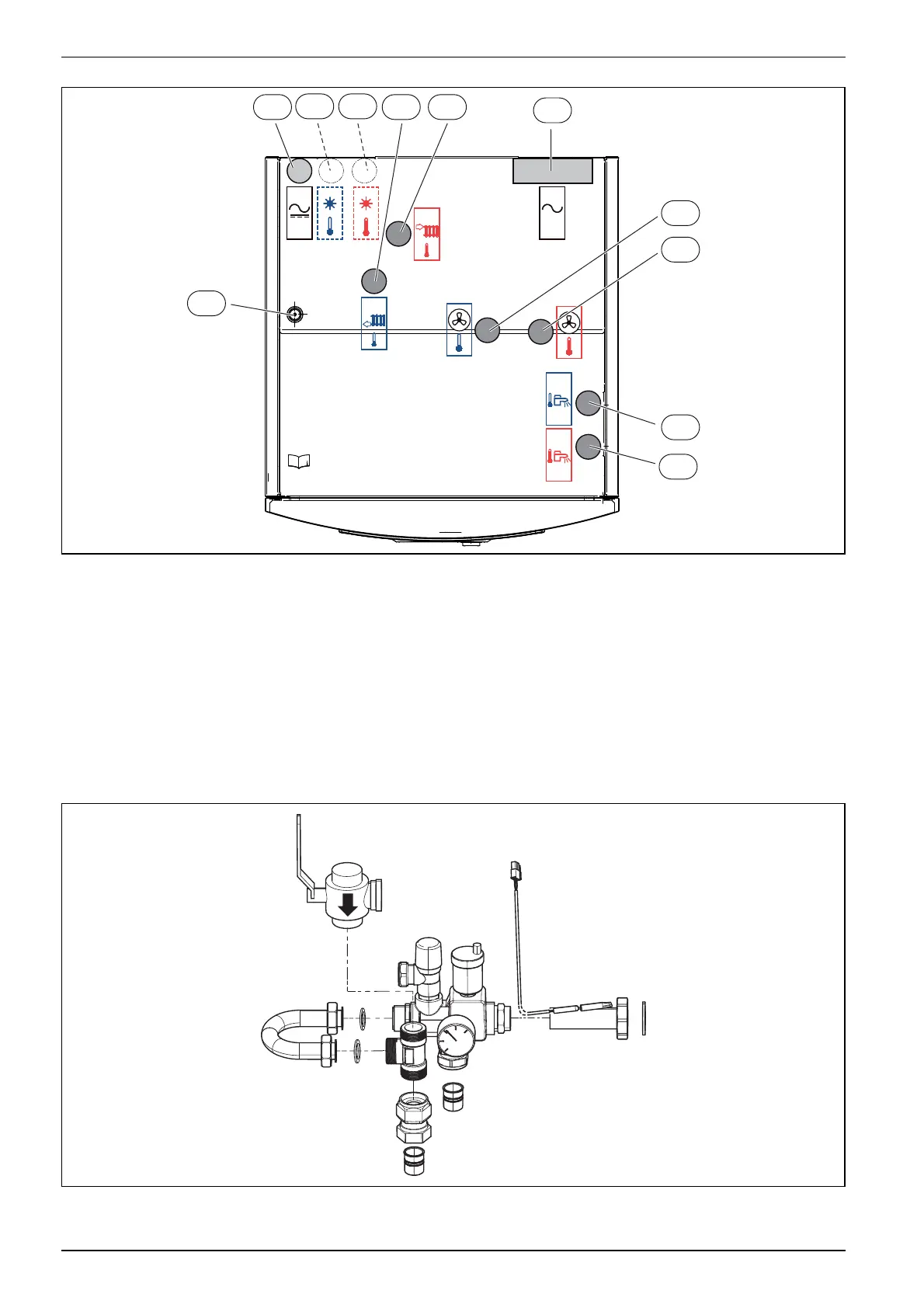
Fig. 8 Heat pump module connections
[1] Heat transfer medium out (to the heat pump)
[2] Heat transfer medium in (from the heat pump)
[3] Cold water inlet connection
[4] DHW outlet connection
[5] Cable feed to IP module
[6] Cable bus CAN-BUS and sensor
[7] Return to solar thermal system (only on the solar models)
[8] Flow from solar thermal system (only on the solar models)
[9] Return from safety group
[10] Flow to safety group
[11] Cable bus electrical connection
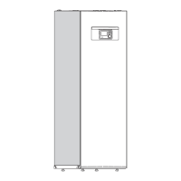
5.1.1 Safety assembly
Fig. 9 Safety assembly delivery
6 720 809 156-08.2I
<50V
230V
/
400V
1
2
4
5
9 106
3
11
7 8
6 720 809 156-12.2I