Electric installation
AirModule 6 720 813 268(2014/10)
28
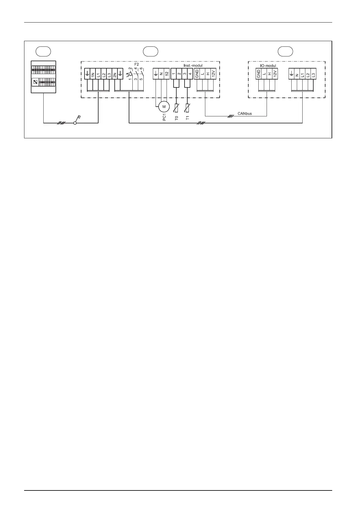
8.7.6 Circuit diagram 15 kW immersion heater 3N~, standard setting
Fig. 28 Circuit diagram 15 kW 3N~
[1] Distribution board
[2] Heat pump module 15 kW, 400 V 3 N~
[3] Heat pump 13/17, 400 V 3 N~
[PC1] Heating system circulation pump
[T0] Flow temperature sensor
[T1] Outside temperature sensor
1
2 3
6 720 809 156-34.2I