Technical information
AirModule –6 720 813 268(2014/10)
9
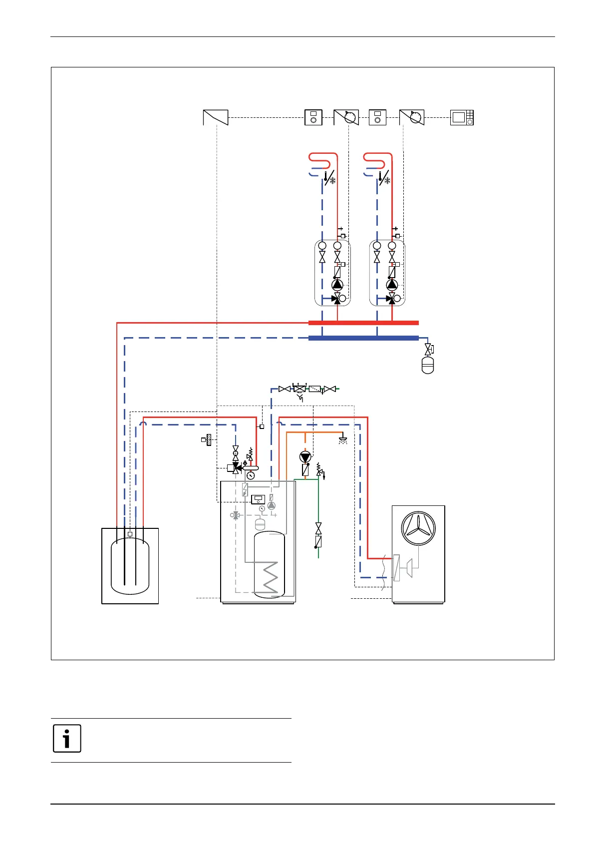
4.2.4 Heat pump, heat pump module and buffer cylinder system configuration
Fig. 4 Heat pump with heat pump module and buffer cylinder
[3] Installed in the heat pump module.
[4] Installed either in the heat pump module or mounted to the wall.
[5] Installed on the wall
MC1
TC1
M
VC1
T
T
PC1
4
HCM2000
2
Airmodule E..
400V AC
PW2
T1
M
VC0
MC1
TC1
M
VC1
T
T
PC1
4
HCM2000
1
400 /230 V AC
AirX ..
5
RTH2000
5
RTH2000
MK2
3
Rego 2000
3
Installermodul
B
AB
A
BC 100/120
T0
6 720 809 156-22.3I
The extra expansion vessel for the heating system is
designed primarily for the volume of the buffer cylinder.