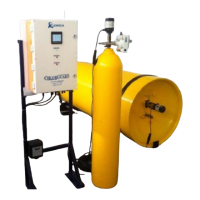
4 FUNCTIONAL DESCRIPTION
4.1 Control Panel
The Control Panel is IP65 rated cabinet that consists of the following elements and functions:
PLC- Programmable Logic Controller
Back-Up Power Supply
UPS Power Supply
Relay Interface
GPSM Modem Module
Solenoid Vale (Only for Pneumatic Version)
Pressure Switch (Only for Pneumatic Version)
External Contacts Analogue Plug Inputs
Mains Power Input
Chlorine Sensor Pin Inputs
Electric Actuator Pin Inputs
Pneumatic Actuator Inputs
4.1.1 PLC- Programmable Logic Controller
Function:
The touch screen PLC manages the operating function for the ChlorGuard 7 system.
Each ChlorGuard 7 system PLC is programmed prior using standard logic. Once the PLC is
programmed and set there is no further need to adjust the PLC and therefore maintains the integrity
of the ChlorGuard operating system
Touch Screen
The touch screen displays the following:
Chlorine Alarm
Actuators Closing
Health Status
Menus and Functions
Just press the screen to activate the menus.
Menus
Refer to screen menus page 28.
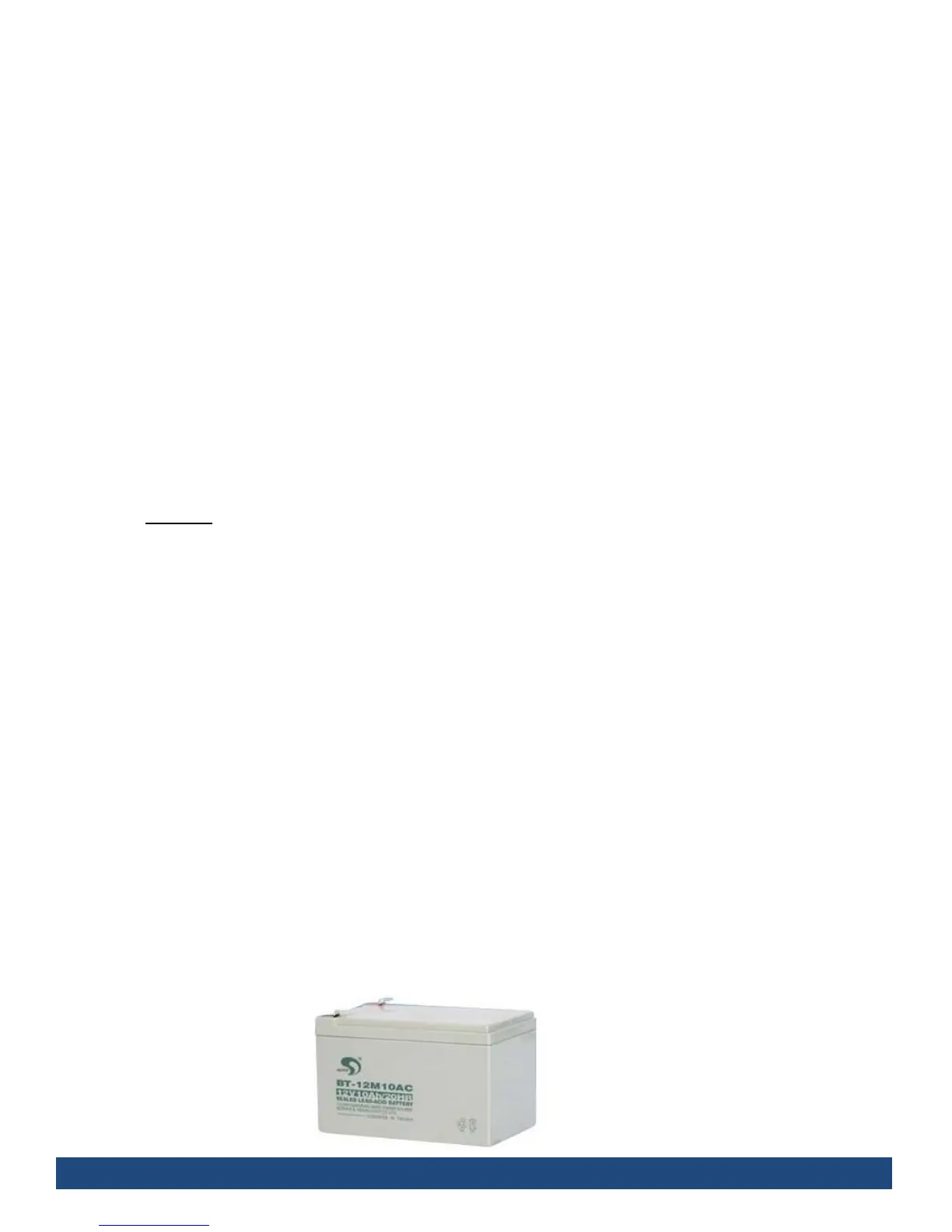
4.1.2 Back-Up Power Supply
The Back-Up power supply provides uninterrupted 24 volt power supply.
Consists of 2x12 Volt Seth batteries which provide sufficient charge to maintain power for at
least 4 hours power under load and up to 24 hours in backup mode.
 Loading...