TABLE OF CONTENTS Page
1 General ...................................................................................... 5
1.1 Typical Setup (70 kg cylinders) ..................................................................... 5
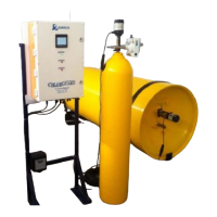
1.2 Typical Setup 920Kg Drums.......................................................................... 6
2 Key Components ...................................................................... 7
2.1 Control Panel ................................................................................................ 8
2.1.1 DC (UPS) power supply ........................................................................................ 11
2.1.2 PLC (Programmable Logic Controller) .................................................................. 11
2.1.3 GMS wireless module ........................................................................................... 11
2.1.4 Warning LED’s: Visual Alarm ................................................................................ 11
2.2 Support Bracket .......................................................................................... 12
2.3 Connecting Transmitting Key ...................................................................... 12
2.4 Actuator Types ............................................................................................ 13
2.5 Chlorine Transmitter & Sensor .................................................................... 13
3 OPERATION ............................................................................ 15
3.1 Overview ..................................................................................................... 15
3.1.1 Power Supply ........................................................................................................ 15
3.1.2 Battery Back-Up .................................................................................................... 15
3.1.3 PLC Programmable Logic Controller ..................................................................... 15
3.1.4 DC (UPS) power supply ........................................................................................ 15
3.1.5 Chlorine Sensor/Transmitter ................................................................................. 15
3.1.6 Closing Actuators .................................................................................................. 16
3.1.6.1 Electric Actuators ................................................................................................................. 16
3.1.6.2 Pneumatic Actuators ............................................................................................................ 16
3.1.6.3 Air Regulator ........................................................................................................................ 16
3.1.6.4 Air Pressure Switch .............................................................................................................. 16
4 Functional Description ........................................................... 17
4.1 Control Panel .............................................................................................. 17
4.1.1 PLC- Programmable Logic Controller.................................................................... 17
4.1.2 Back-Up Power Supply ......................................................................................... 17
4.1.3 Relay Interface ...................................................................................................... 18
4.1.4 GSM Modem ......................................................................................................... 18
4.1.5 Solenoid Valve (Pneumatic Version Only) ............................................................. 18
4.1.6 Pressure Switch (Pneumatic Version Only) ........................................................... 18
4.1.7 SCADA Digital Outputs ......................................................................................... 19
4.1.8 Mains Power Input ................................................................................................ 22
4.1.9 Chlorine Sensor Pin Inputs ................................................................................... 22
4.1.10 Electric Actuator Pin Inputs ................................................................................... 22
4.1.11 Pneumatic Actuator Inputs .................................................................................... 23
4.1.12 Chlorine Transmitter/Sensors ............................................................................... 23