Approved Installation Manual for the Experimental Report No 104
EDM-350 Page 10 of 46 Rev A
Engine Data Management System Date 7-10-2021
5. EDM Display Installation
Choose the Proper Installation Location
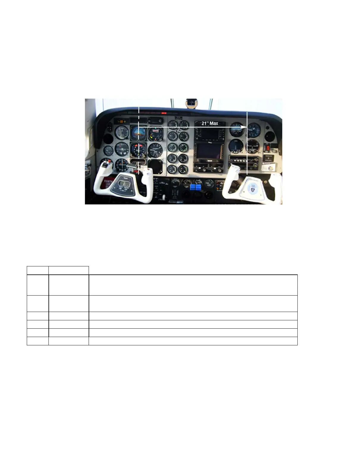
The display is best located within the natural scan and easy reach of the pilot. The recommended mounting location
is defined as the distance from the vertical centerline of the Primary Flight Instruments to the outer edge of the
further most gauge displayed on the EDM.
6. Routing the Wiring Harnesses
Five connectors are protruding from the rear of the instrument. Connect the five wiring harnesses to the rear of the
instrument and run the cables through the firewall into the engine compartment. Allow sufficient service loop to
facilitate removal of the connectors for servicing. These wiring harnesses are labeled as follows:
P1 790200 Power, Engine ground, MFD input, MFD output the following are optional and need
to be added : Oil temperature, Induction temperature, Carburetor temperature,
Outside air temperature, Turbine inlet temperature, Turbine inlet temperature 2,
P2 700700
CHT, EGT 6 cylinder
Serial data to GPS, Serial data from GPS, Fuel flow transducer
Fuel Pressure, Fuel Level (Resistive and Capacitive ), Amps
Category 5 jack and cable for RAD (Remote Alarm Display)
Route the wires from the connectors through the firewall using rubber grommets and flame retarding silicone. Use an
existing hole if possible. All wires must be routed away from high temperature areas (exhaust stacks, turbochargers,
etc.). Secure probe and sensor leads to a convenient location on the engine approximately 8 to 12 inches from the
probe or sensor, being sure there is sufficient slack to absorb engine torque. It is essential in routing the probe wire
that this wire not be allowed to touch metal parts of the air-frame or engine since abrasion will destroy this high
temperature wire. Secure wires along the route to the indicator. Secure wire using original clamps, tape or tie wrap if
possible.
Note: The probe wires must not be tied in with ignition, alternator or engine cabin heater ignition wires or
transceiver coax cables because of potential induced interference with readings.
The temperature probe wiring harness is made of Chromel-Alumel alloy wires that must not be substituted or
extended with copper wire. Temperature probe leads must be spliced with the same type of wire (typically