Approved Installation Manual for the Experimental Report No 104
EDM-350 Page 9 of 46 Rev A
Engine Data Management System Date 7-10-2021
5. Locating and Installing the Indicator Display (Alert Light)
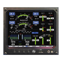
Single Engine Aircraft EDM-350
The EDM-350 display should be located as close as possible to the pilot with an unobstructed view and for
easy access to the buttons on the instrument.
The light for the EDM-350 is mounted in a 3/8” diameter hole.
Mounting bracket for the EDM-350
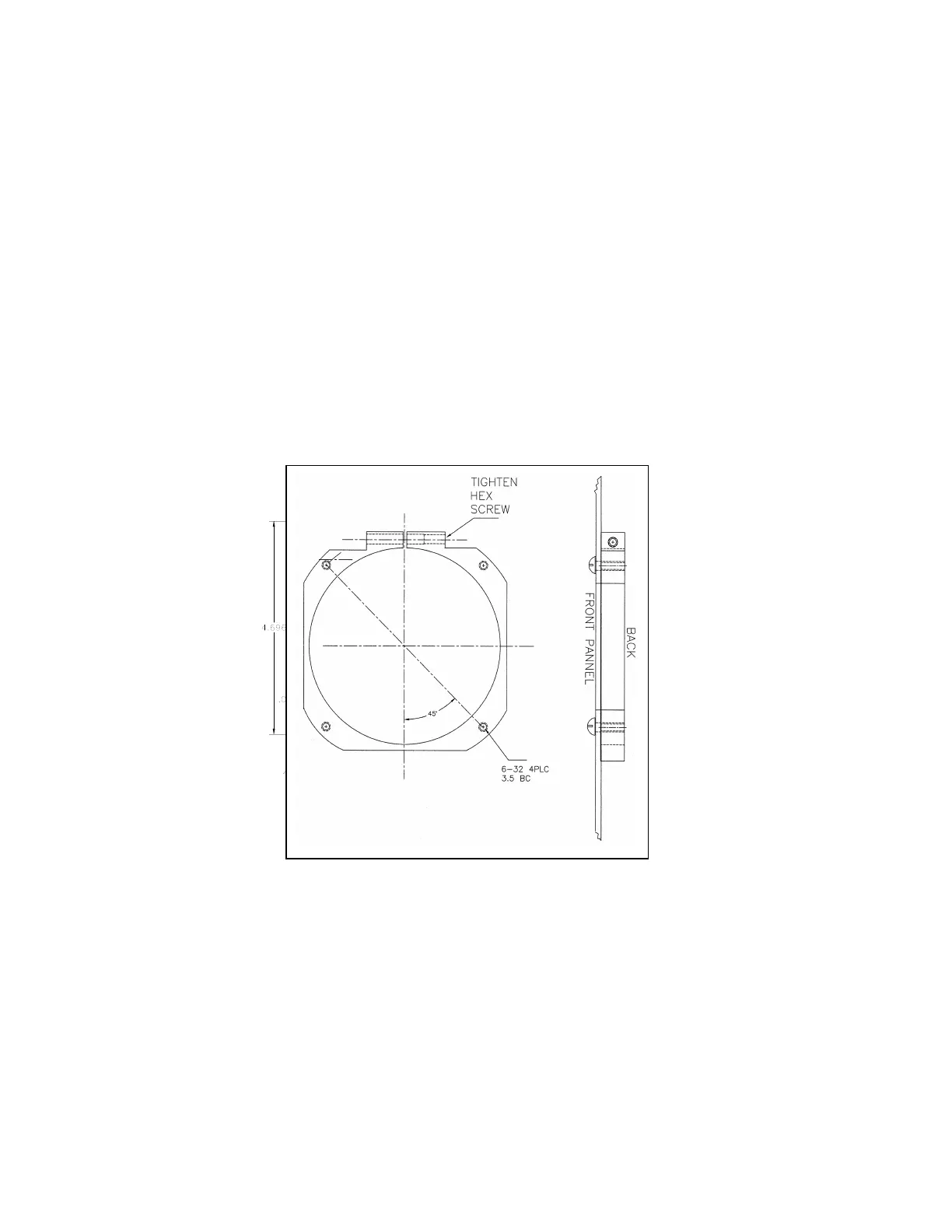
EDM-350 Model: Mounts in a standard 3-1/8” instrument hole. First, place the mounting bracket on the
instrument and tighten the clamp hex screw until you can just remove the instrument from the bracket. The Mounting
bracket is then placed behind the instrument panel hole and screwed (6-32 x ½” screws) in place using the existing
holes. Three screws should be used leaving one hole vacant on either side of the hex screw. Locate the hex screw
in a location that you can easily get to from the rear of the panel. The body of the instrument is 3.0 inches in
diameter and 3.0 inches deep less connectors.