Approved Installation Manual for the Experimental Report No 104
EDM-350 Page 45 of 46 Rev A
Engine Data Management System Date 7-10-2021
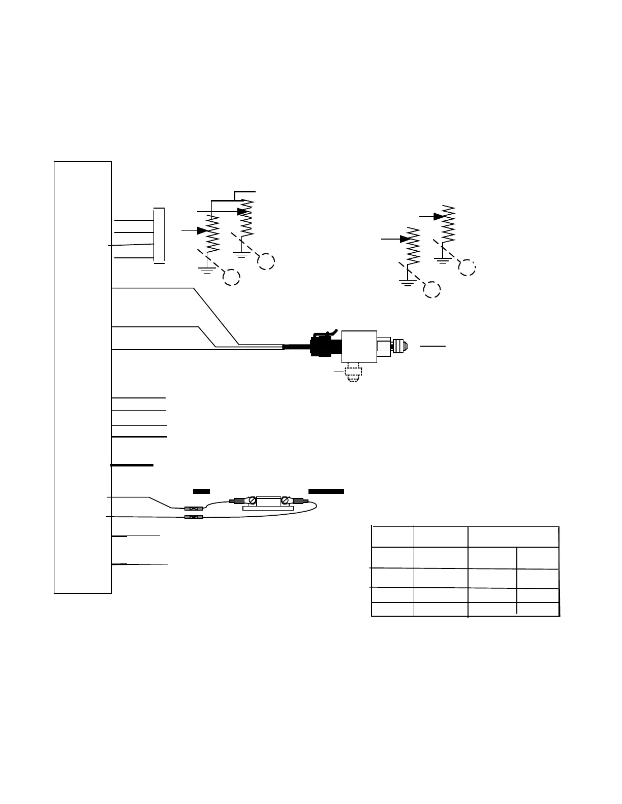
44.1 J5 PN 790723 (fuel tanks, fuel press, amps)
6 red
9 white
1 White
2 Green
5 White
4 Green
7 black
FQ (resistive or voltage senders)
MAIN & AUX tanks
MAIN & AUX tank with Pennycap and Gull require
PN 791802
3 black
10 Green
12 red
14 White+
15 Gray-
AMPS-1
8 White
7 Black
3 Blk
13 white
Aux Pwr IN optional
11 Red
Sig-1
Sig-2
+5vdc
Green
sig-2
pin 2
White
Sig-1
pin-1
Gnd
X2 Blk pin 3
Ground at Sender
+
Sig-3
Sig-4
Gnd
+5 vdc
Signal
Sig-1
Sig-2
Sig-4
Sig-3
SINGLE
L-MAIN
R-MAIN
FUEL TANK CONFIGURATION
PN 790723
Fuel Press Sig+
iFuel Pressure 0-50 PSIG
PN 159935A
or
0-100 PSID PN 159938 (Differential
Pressure)
Electrical Connections are the same for
both
PN 159935A
or 159938
Ground
Power 5vdc
Signal AMP +
Fuel-P
Differential port for upper deck pressure
PN 159938
PN 159920
FUSE 1A
VDO Oil P
Pin 7&8
-
100 A Shunt
External
Source
8-14vdc to
CIES
Frequency
Green
sig-2
pin 2
White
Sig-1
pin-1
Main
Aux