Do you have a question about the JABSCO 6400 Series and is the answer not in the manual?
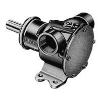
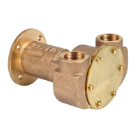
Details pump construction like body, impeller, shaft, wearplate, seal, bearing, and ports.
Lists specific model numbers and their corresponding descriptions for different pump configurations.
Outlines the various uses for the pumps, including marine, industrial, farm, and home applications.
Covers installation, drive methods, warnings, and important notices for safe pump operation.
Provides guidance on speeds, self-priming, running dry, fluid compatibility, pressures, temperatures, and freezing.
Step-by-step guide on how to take apart the pump, including removing covers, impellers, seals, and bearings.
Step-by-step guide for reassembling the pump, focusing on seal lubrication, wearplate, and bearing installation.
Visual representation of the pump with numbered parts for identification.
Detailed list of all pump components with quantities required and their corresponding part numbers.
Presents performance data (GPM, HP) at various RPMs for different impeller types and pressure settings.
Provides key physical dimensions and port locations for the 6400 and 7420 series pumps.
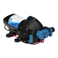
The Jabsco 6400-Series and 7420-Series pumps are self-priming devices designed for a wide range of liquid transfer applications across marine, industrial, farm, and home environments. These pumps are built with a bronze body, neoprene impeller, Type 316 stainless steel shaft, and a replaceable wearplate, ensuring durability and reliable performance. The shaft seal is a carbon-ceramic face type, and the pump incorporates a pre-lubricated double row ball bearing for smooth operation.
These pumps are primarily designed for transferring various liquids. In marine settings, they are suitable for pumping bilges, washdown tasks, and engine cooling. Industrially, they are used for circulating and transferring liquids, velocity-mixing, and handling substances like soap, liquors, pastes, glues, glycerine, lotions, and brine. On farms, they assist with pumping water for livestock and poultry houses, as well as booster pumping. For plumbing and home use, they are effective for pumping out flooded basements, cesspools, and sumps.
The self-priming capability allows the pump to draw liquid from a dry suction lift. For vertical dry suction lifts of up to 10 feet (3.1m), a minimum of 800 RPM is required. When wetted, the pump can achieve suction lifts of up to 22 feet (6.7m). It is crucial to ensure that suction lines are airtight for optimal priming. The pump's rotation determines the location of its intake and discharge ports, and it can be configured for either clockwise or counter-clockwise rotation by adjusting the impeller blade deflection under the cam.
The pumps can be mounted in any position, offering flexibility in installation. They can be driven by either a belt or a direct flexible coupling. When using a belt drive, it's important to avoid overtightening the belt, as this can reduce bearing life. For direct drive installations, a clearance must be maintained between the drive shaft and the pump shaft. The pump and drive shaft should be mounted and aligned before tightening the coupling set screw. If a drive pulley or coupling needs to be pressed onto the shaft, the end cover and impeller should be removed, and the shaft supported from the impeller end to prevent damage to the pump. Hammering a pulley or coupling onto the shaft is strictly prohibited.
Operating speeds should generally be kept at the lowest possible RPMs within the performance table for extended pump life. While the pump can prime at low or high speeds, continuous dry running should be avoided for more than 30 seconds, as the pumped liquid provides lubrication, and lack of it will damage the impeller.
When pumping light fraction petroleum derivatives, solvents, thinners, highly concentrated or organic acids, users should consult the Jabsco "Chemical Resistance Table" to ensure compatibility with the pump's body materials and impeller compounds. If corrosive fluids are handled, flushing the pump with water after each use or workday will prolong its life.
For continuous operation, the pressure should not exceed 30 psi (2.1 kg/sq cm). For intermittent service, pressures between 35 to 50 psi (2.5-3.5 kg/sq cm) can be achieved using a specific impeller (807-1001) and an extra gasket. The operating temperature ranges vary depending on the impeller material: Neoprene (45°-180° F / 7°-82° C), Nitrile (50°-180° F / 10°-82° C), and Natural Rubber (33°-120° F / 0.6°-49° C).
In freezing temperatures, the unit should be drained by loosening the end cover. Compatible anti-freeze compounds include Atlas "Permaguard," DuPont "Zerex" and "Telar," Dow Chemical "Downguard," Olin Mathison "Pyro," and most methyl alcohol (methanol) based anti-freezes. Petroleum-based anti-freeze compounds or rust inhibitors should not be used.
Regular maintenance involves inspecting all parts for wear or damage and replacing them as necessary. A standard pump gasket, which is 0.015" thick, should be used; a thicker gasket can reduce priming ability, while a thinner one can cause the impeller to bind. To prevent costly shutdowns, it is recommended to keep a Jabsco Service Kit on hand.
Disassembly for maintenance or repair involves removing the end cover screws, end cover, and gasket, followed by the impeller (and O-ring for -10XX pumps). The seal, seal seat, and gasket are then removed using a hooked wire. The cam screw is loosened, the cam removed, and any sealant cleaned off. The wearplate is also removed. The outer bearing seal is pried out, followed by the bearing-to-body retaining ring. The shaft and bearing assembly are pressed out, with heating the outside of the body at the bearing easing disassembly. The bearing-to-shaft retaining ring is removed, and the shaft is pressed through the bearing while supporting its inner race. Finally, the inner seal is pried out.
Assembly is the reverse process, starting with lubricating and pressing the inner seal into the body bearing seal bore with the lip facing away from the bearing bore. The shaft is pressed into the bearing, supporting the inner race, and the bearing-to-shaft retaining ring is installed. For 6400-Series pumps, the slinger is positioned in the body drain area. The bearing and shaft assembly is pressed into the bore, and the bearing-to-body retaining ring is installed. The outer bearing seal is lubricated and pressed flush with the body. The wearplate is installed, aligning its slot with the dowel pin. A thin coat of sealant is applied to the cam screw threads before installation. The seal seat assembly is lubricated with water and inserted into the seal bore with the polished surface facing outward, ensuring the gasket is seated firmly. The carbon ring assembly is slid over the shaft with the carbon facing ceramic. For -10XX series pumps, the O-ring is positioned in its groove. The impeller bore is lubricated with water pump grease, and the impeller is started into the bore with a rotary motion until splines engage, then pushed in. Finally, the gasket and end cover are installed and secured with screws.
A warning is provided regarding injury hazards from exposed pulleys and belts, advising the installation of a shield and keeping clear while machinery is operating.
| Series | 6400 |
|---|---|
| Type | Flexible Impeller |
| Max Speed | 3000 RPM |
| Impeller Material | Neoprene |
| Rotation | Reversible |
| Drive Type | Belt Drive |
| Self-Priming | Yes |