3. INSTALLATION
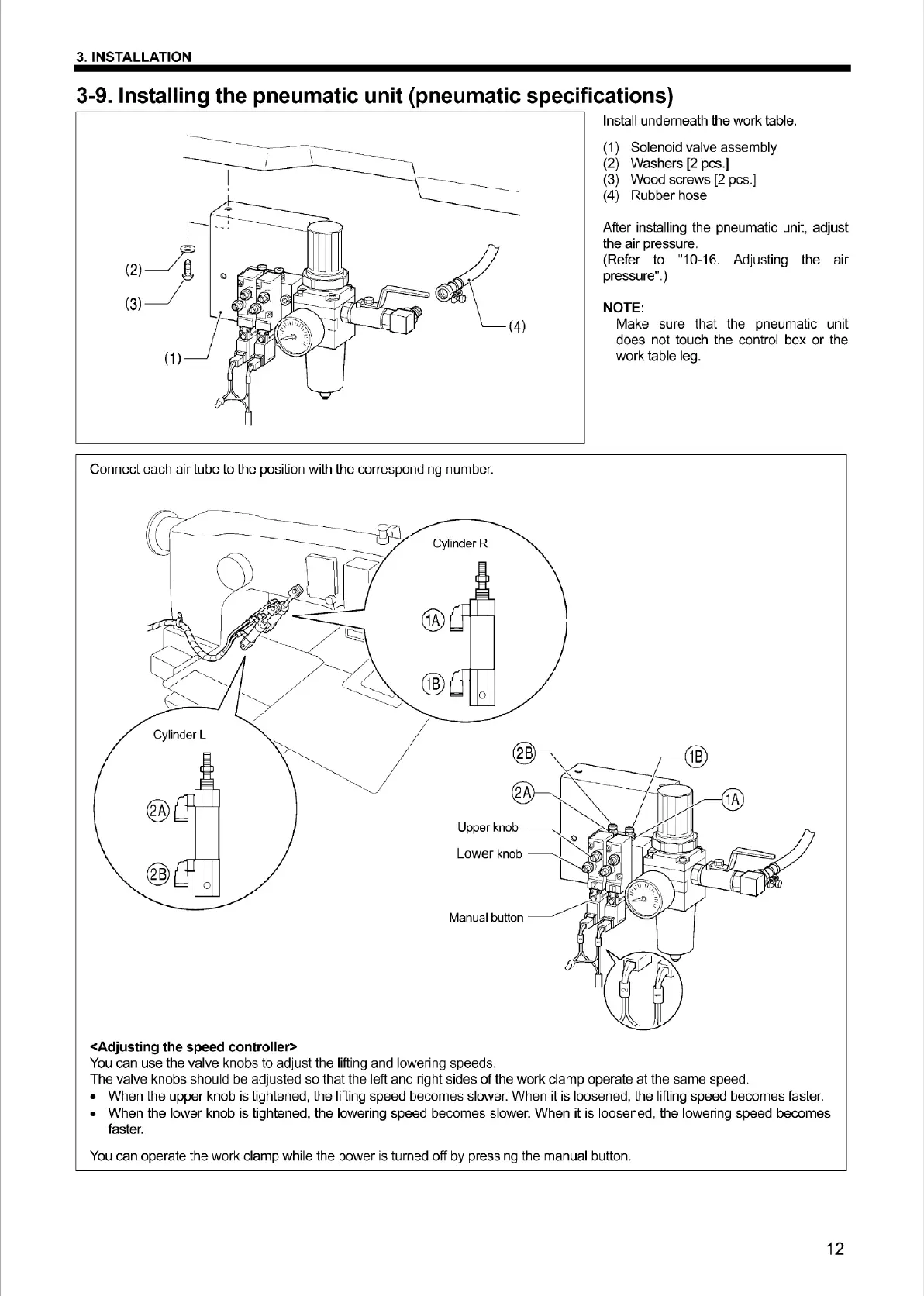
3-9. Installing the pneumatic unit (pneumatic specifications)
-------------------
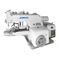
Connect each air tube to the position with the corresponding number.
Lower
knob
Man
ual
button
<Adjusting the speed controller>
You can use the valve knobs
to
adjust the lifting and lowering speeds.
Install underneath
the
wo
rk t
ab
le.
(1) Solenoid valve assembly
(2) Washers [2 pcs.]
(3) Wood screws [2 pcs.]
(4) Rubber hose
After installing
the
pneumatic unit, adjust
the air pressure.
(Refer to "10-16. Adjusting the
air
pressure".)
NOTE:
Make sure that the pneumatic unit
does not touch the control box
or
t
he
work table leg.
1A
The valve knobs should be adjusted
so
that the left and right sides
of
the work cl
amp
operate
at
the same speed.
• When
the
upper
knob
is
tightened, the lifting speed becomes slower. When it is loosened, t
he
lifting speed becomes faster.
• When the lower knob
is
ti
gh
tened, the loweri
ng
speed becomes slower. Wh
en
it is loosened, the lowering speed becomes
faster.
You can operate the work clamp while
the
power is turned off by pressing the manual button.
12
From the library of Superior Sewing Machine & Supply LLC - www.supsew.com