GB-9
JACOBSEN AR3
NARROW WIDTH OF CUT FIELD KIT
FITTING INSTRUCTIONS
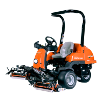
4.5 CONTINUED
5. Reassemble hardware (D, E and Nyloc Nut)
removed in Step 4.2.1 to Ram Pin (B) and Lift
Arm (A).
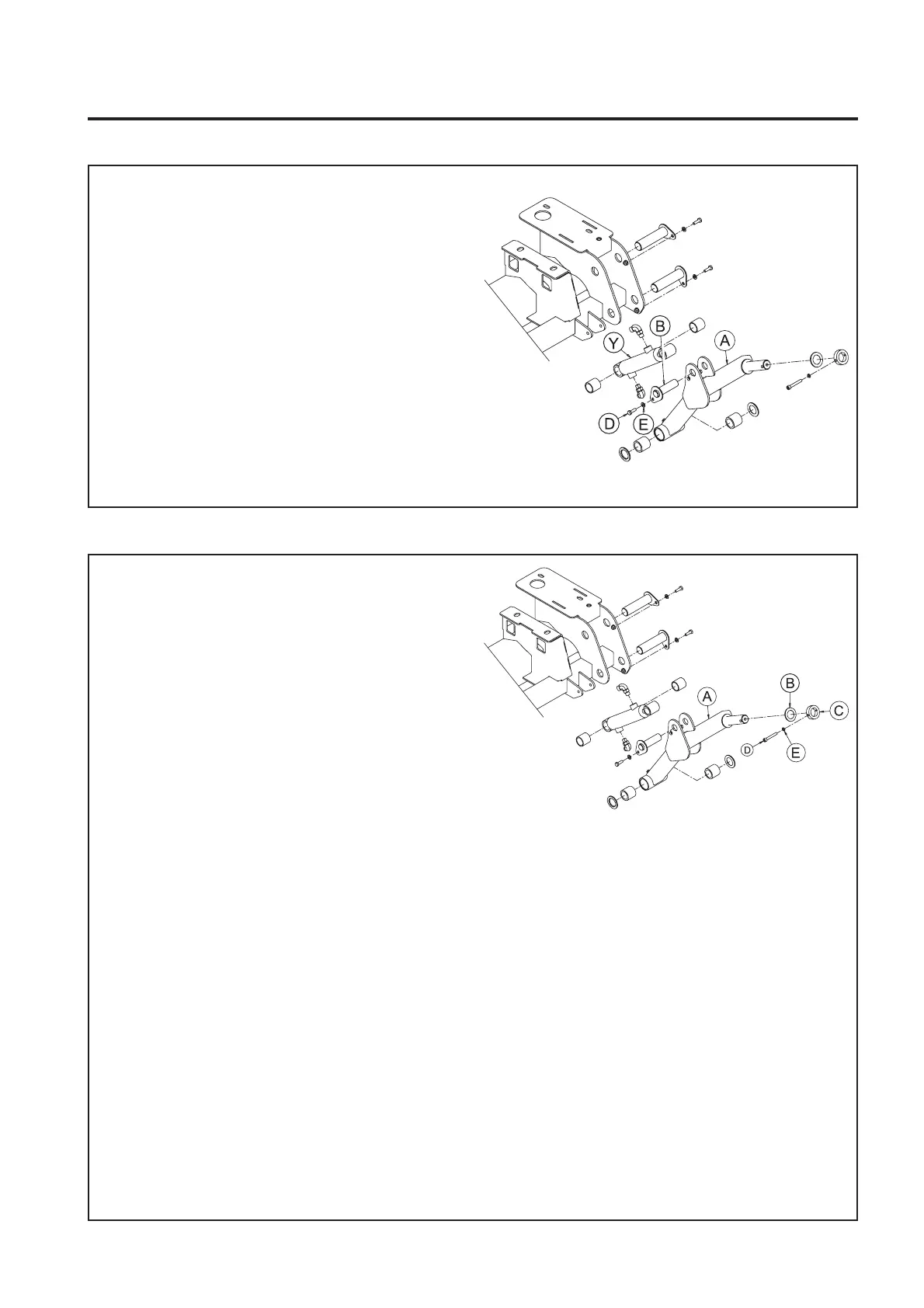
4.6 ASSEMBLE CUTTING UNIT TO LIFT ARM
1. Assemble Thrust Washer (B) to Lift Arm (A)
Pivot Shaft so that on assembly it will be
located between the Lift Arm (A) and the Yoke
Pivot Housing.
2. Smear surface of Lift Arm (A) Pivot Shaft with
Shell Darina R2 grease (or equivalent).
3. Assemble Cutting Unit to Lift Arm (A) Pivot
Shaft.
4. Assemble Clamp Collar (C) removed in Step
4.1.1 to Lift Arm (A) Pivot Shaft.
5. Align holes in Clamp Collar (C) and Lift Arm (A)
Pivot Shaft.
6. Reassemble hardware (D and E) removed in
Step 4.1.1
4 FRONT LH LIFT ARM
 Loading...