SPECIFICATIONS AND GENERAL INFORMATION
4241262-Rev B 2-3
2
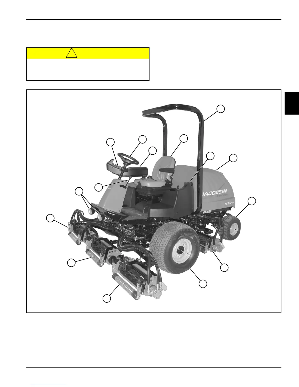
Component Location
See Figure 2-4.
!
CAUTION
Figure 2-4: Component Location
Become familiar with operator controls, machine
components, and correct operating procedures
before beginning repair procedures.
1 OPS 6 Left Front Wheel 11 Throttle Lever
2 Hydraulic Oil Tank 7 Left Front Cutting Unit 12 Instrument Panel
3 Hood 8 Center Cutting Unit 13 Steering Wheel
4 Left Rear Wheel 9 Right Front Cutting Unit 14 Armrest Assembly
5 Left Rear Cutting Unit 10 Work Lights 15 Seat
TN3586
1
3
4
13
15
12
9
8
7
5
6
2
14
11
10
 Loading...