4 ADJUSTMENTS
18
4.5 FLASH ATTACH
™
_________________________________________________________
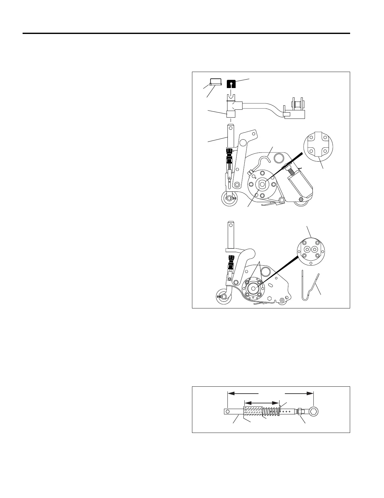
Installing Cutting units
1. Place each cutting unit in front of its respective lift arm.
Raise lift arm and position cutting unit so that yoke (T) is
in line with swivel housing (S). Carefully lower arm onto
yoke. Insert pin (K) through hole in yoke, fasten
retaining clip (L), and install cap (M).
2. Assemble motors (N), with hoses attached, to the
cutting units. Clean motor splines and coupling. Apply
Moly 2 EP grease to the female spline on reel.
Thoroughly clean the motor mounting surface. Slide
motor into bearing housing. On 5 in. reels lock motor in
place by inserting two motor clips (O), with loops facing
center of motor, into mounting pins (P). On 7 in. reels
hand tighten key (Q) on bearing housing.
3. Raise reels and install down pressure spring pins (V,
Figure 4F). If cutting height has not changed, set pins
in same position they were in when reels were
removed.
Removing Cutting Units
1. Lower reels to the ground and remove down pressure
spring pins (V, Figure 4F). Make note of where springs
are set.
2. On 5 in. reels, remove motor clips (O). On 7 in. reels
loosen key (Q) on motor housing. Pull motor straight
out from cutting unit.
3. Carefully place motor and its hoses away from the
cutting unit. To prevent contamination and damage to
internal components cover or cap off bearing housing
cavity (R).
4. Remove cap (M) on lift arm. Unfasten retaining clip (L)
from pin (K) and remove pin.
5. Carefully raise arm until cutting unit can be removed.
Figure 4E
4.6 DOWN PRESSURE ________________________________________________________
Each reel is equipped with a down pressure spring. Down
pressure improves cutting quality by ensuring consistent
contact between the reel and ground. Check and adjust
down pressure any time cutting height has been changed or
to optimize the cut for best performance.
1. With reels raised, place pin
(V) in 4th hole from ball
joint. Lower reels onto a flat surface before measuring
down pressure.
2. Initially set distance between ball joint center and rod
cross pin center to 8-15/16 in. ± 1/16 in. (227 mm ± 2
mm). To adjust length, loosen lock nut
(W) and turn
rod
(U) in or out of ball joint.
3. Measure length of spring as shown on all 5 reels.
Record the shortest spring dimension and set the other
springs by adjusting rods
(U) to that dimension ± 1/16
in. (2 mm). The rod cross pin must be horizontal, then
tighten locknut (
W).
4. To adjust down pressure, move pin one hole towards
spring to increase pressure, or one hole away from
spring to decrease pressure on rear roller.
Figure 4F
7 IN. REELS
5 IN. REELS
T
S
K
L
M
N
O
P
Q
R
LF010
N