Page 11
remove the short cabinet panel from the front of the spa to allow you
to feed the cable through to the control box. Install the cable with
connector through the large opening provided in the bottom of the
control box.
9. Install control box door and reinstall the cabinet side panels.
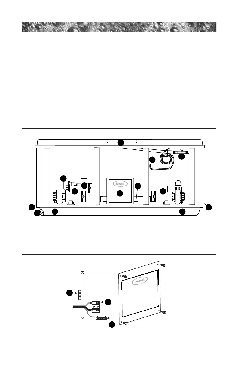
Figure-B (Control Box)
10
4
3
2
2
2
1. Terminal Block
2. Bonding Lug
3. Grounding Terminal
TB1
TB3
Figure-A (Equipment Area)
1. Control Box
2. Power Supply Entrance(s)
3. Jets Pump #1
4. Heater
5. Spa Drain Valv e
6. Pump Drain Plug(s)
7. Jets Pump #2
8.
9. Optional CD Ozonator (Purchased Separately)
10.
1
Flow
Note: Pump Locations Vary by Model
5
6
6
9
8
7
6
3
1
11. Control Panel
11