JacuzziSignatureWaterHeatersJ‐S180/J‐S199 21
InstallaonofTemperatureController
ControllerLocaon
MounngtheController
CableLengthsandSizes
• Thecontrollershouldbeoutofreachofsmall
children.
• Avoidlocaonswherethecontrollermaybecome
hot(neartheovenorradiantheater).
• Avoidlocaonsindirectsunlight.Thedigital
displaymaybedifficulttoreadindirectsunlight.
• Avoidlocaonswherethetemperaturecontroller
couldbesplashedwithliquids.
• Donotinstallinlocaonswhereitcanbe
adjustedbythepublic.
Indoormodelshavetheircontrollerbuiltintothe
frontpanel.Addionalcontrollerscanbeinstalled.
Thecableforthetemperaturecontrollershouldbea
non‐polarizedtwo‐corecablewithaminimumgauge
of22AWG.
Themaximumcablelengthfromeach
controllertothewaterheaterdependsonthetotal
numberofwiredcontrollersconnectedtothewater
heater.Controllersneedtobewiredinparallel.
IffourJ‐C100controllersareinstalled,simultaneously
pressthePriorityModeandPowerbuonsonthe
fourth
controllerunlabeepsounds.
Numberof
Controllers
MaximumCableLengthforeach
ControllertoWaterHeater
1 328(100m)
2 164(50m)
3or4* 65(20m)
Turnthepoweroff.Donotaempttoconnectthe
temperaturecontrollerswiththepoweron.Although
thecontrollerisalowvoltagedevice,there is 120volt
potenalnexttothetemperaturecontroller
conneconsinsidetheunit.
Donotconnectthetemperaturecontrollertothe
120VAC
terminalsprovidedfortheoponalsolenoid
drainvalves.
WARNING
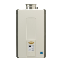
1. Makethreeholesinthewallasshown.
2. Runthecablebetweenthecontrollerandthe
waterheaterorthecontrollerandanother
controller.
3. Removethefaceplatefromthetemperature
controllerusingascrewdriver.
4. Connectthecabletothetemperaturecontroller.
5. Mountthecontrollerto
thewallusingtheholes
drilledinstep1.
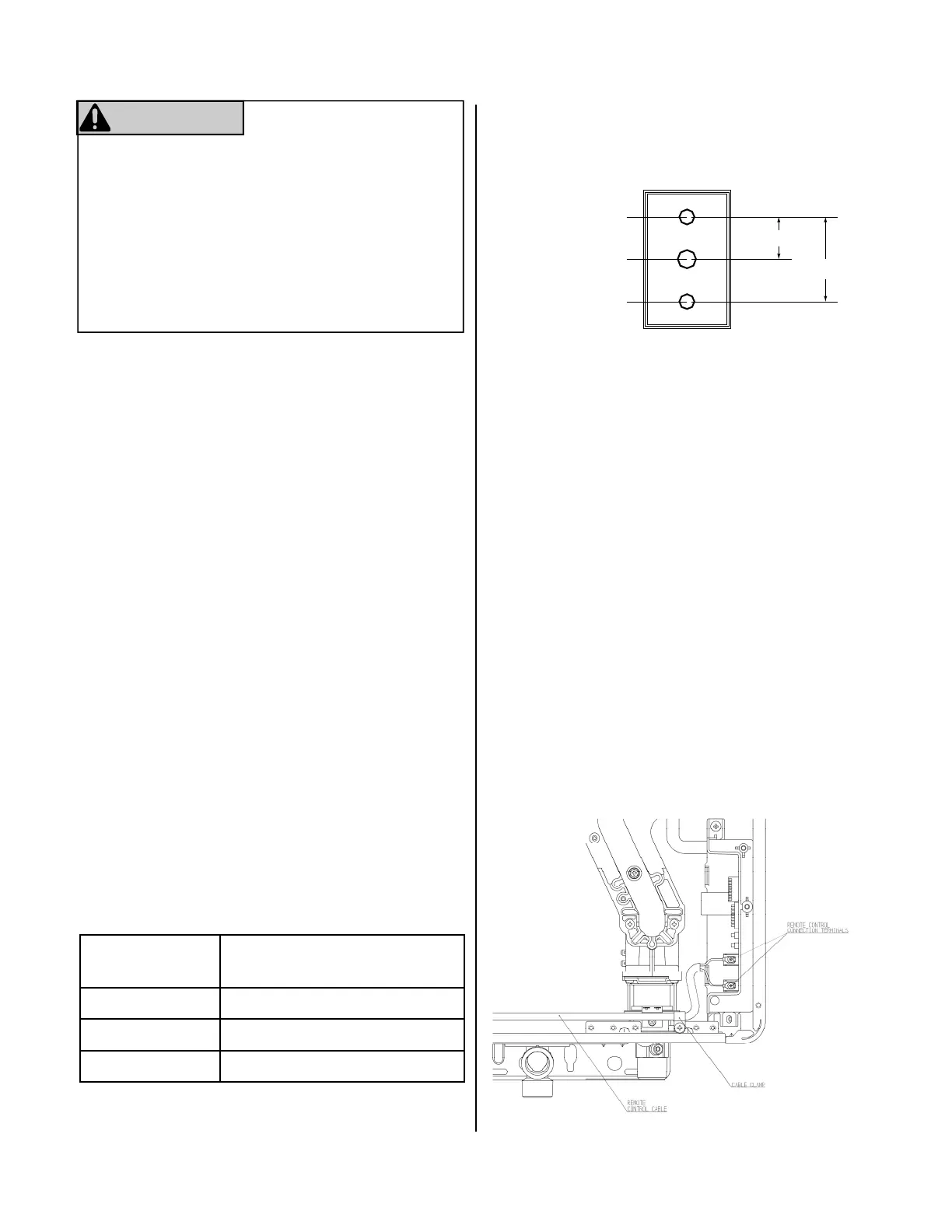
6. Disconnectthepowerfromthewaterheater.
7. RemovetheplasccoverfromthePCBand
electricalconnecons.
8. Threadthecablethroughtheaccessholeatthe
baseoftheunitandconnectthewirestothe
controllerterminalsontherighthan dsideboom
ofthePCB.
9. Securethecontrollercableusingtheclamp
provided.
10. ReplaceplasccoveroverPCBandthenreplace
thecoverofthewaterheater.
Outline of Remote
securing screw
1-21/32"
3-5/16
securing screw
wiring hole
*Only3addionalcontrollerscanbewiredtothe
indoorwaterheater.
 Loading...