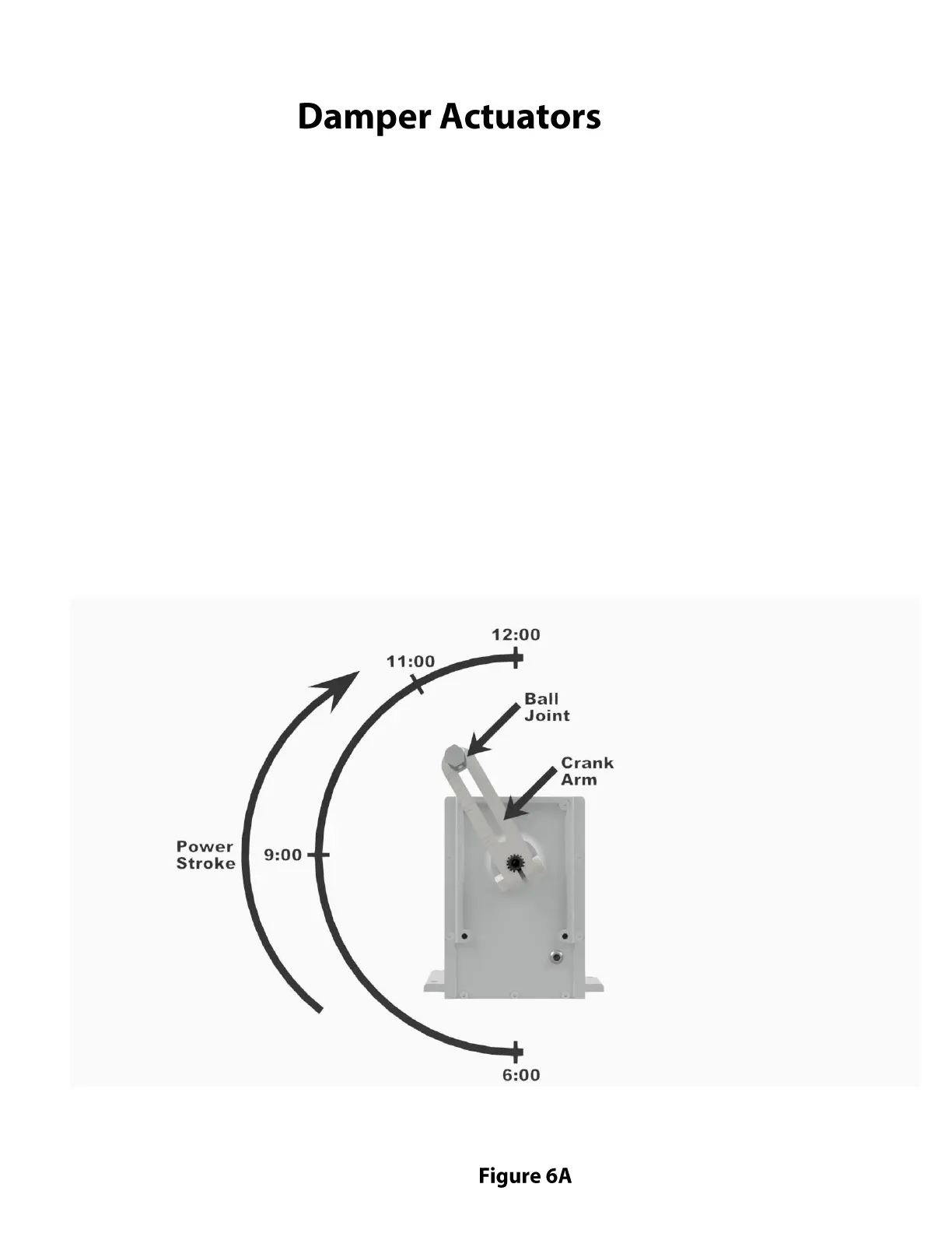
Actuator is shown in energized mode
(clockwise travel, full stop position) with
crank arm installed in recommended
position. This is the "damper open" position
Oyler Pits utilize two damper actuators, one for temperature control and one for the “ Evac” mode.
Older units have Barber-Colman actuators and newer units have Schneider Electric actuators. They
are identical, other than the name, as Schneider acquired Barber-Colman. Instructions for the actuators
are included in this manual (see the Thermostats and Actuator Manuals section). The model for 120 Volt
units is MA-418.
These actuators are located on the top rear of the pit near the chimney connector. IMPORTANT: When
replacing or adjusting the actuator, it is critical that the motor is energized and allowed to reach its full
stop position before connecting the linkage rod from the dampers to the ball joint on the “crank arm”
(during the power stroke the output shaft travels 180 degrees shaft to reach its stopping point). If the
actuator cannot reach this stopping point, it will overheat and fail. With the actuator energized, the crank
arm should be installed so that it is in the 11 o’clock position or approximately 150 degrees from the
vertically down position (see drawing). After installing the crank arm in the proper position and connecting
the linkage rod (with the associated dampers open*) to the ball joint on the crank arm, the device should
be cycled (off and on) several times to make sure there is no binding in the linkage components which
would shorten the travel of the power stroke. Also, make sure the appropriate dampers fully close when
the actuator is de-energized. It is also recommended that this test phase also include the use of an amp
meter to determine that the actuator has in fact reached its full travel stop position when energized. The
amp reading for 120 Volt units should drop from approximately 0.9 A (running) to 0.3A (stopped or holding).