Page 15
3.4 Heater Connection
The heater connection section applies to all
heaters or heat pumps with thermostatic circuitry
of 24 VAC or less (see pages 15 thru 17 for brand
specific installation).
NOTE If you are connecting a heater with thermostatic
circuitry of 120 VAC or greater, do not connect
to the green, 10-pin Terminal Bar. Instead
connect the heater to a high voltage relay in the
Power Center and plug the spare relay into the
Electric Heater relay socket on the back of the
Power Center PCB.
3.4.1 JandyHeaterConnections
1. Connect two #14 gauge wires, designed for
use in hot environments, to the #1 and #2
terminals on the green, 10-pin Terminal Bar.
2. Connect the other ends of the #14 gauge
wires from Step 1 to the Fireman's Switch
terminal bar in place of the factory installed
wire loop.
3. Do not disconnect high limit or pressure
switches.
4. Turn the heater thermostat(s) to maximum
setting.
5. Turn the heater switch to the ON position.
For dual thermostat heaters turn switch to
Spa position.
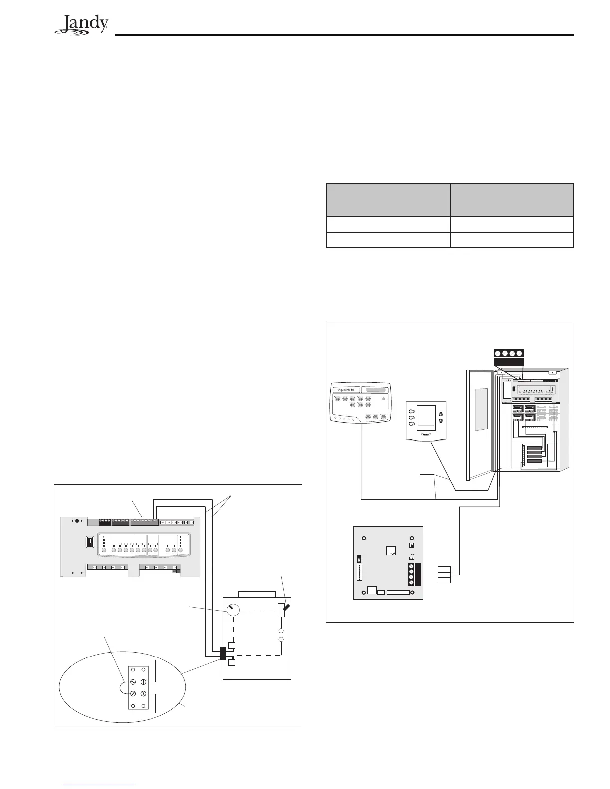
Figure 9. Jandy Heater Connection
Power Center PCB/Bezel
Heater
Wiring
#14
Gauge
Wire
Green 10-pin
Terminal Bar
Heater
Thermostat To
Max.
Heater Toggle
Switch To On
Terminal 1
Terminal 2
Jandy Heater Fireman's
Switch Connection
Factory
Installed
Wire Loop
3.4.2 GuidelinesforSophisticatedDiagnostic
CommunicationtoJandyLXHeaters
1. Remove the LX GUI from the heater.
2. Confirm the LX and AquaLink RS software
revisions are compatible (see table).
3. Run a 4-conductor cable from the LX GUI
red, 4-pin connector to the RS power Center
red, 4-pin connector (see Figure 10).
LX Software Revision AquaLink RS Software
Revision
C04 to C08 H or HH
C10, C11 or later I, JJ, K or later
NOTE If connecting more than two (2) items to the RS
Power Center red, 4-pin connector, a Multiplex
PCB is required.
OPTIONAL
4 3 2 1
4 3 2 1
RED
BLK
YEL
GRN
RED
BLK
YEL
GRN
®
JANDYAquaLinkRS
FILTERPUMPOFF
AIR 79°
06/26/04 MON
6:00 PM
EQUIPMENT ON/OFF
ONETOUCH ON/OFF
MENU / HELP
4-Conductor
Wire
LX GUI
OR
RS Power
Center
Figure 10. Jandy LX Heater Connection to Power
Center
 Loading...