Caution: Always turn off all circuits and then turn off power before moving DIP switches. If AUX 1, 2, or 3
were programmed to operate automatically, clear the programs before turning on the appropriate clip switch.
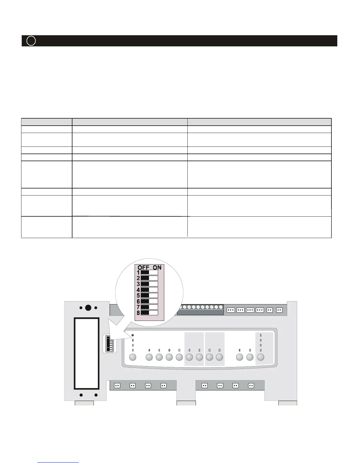
All DIP Switches are located on the left side of the Power Center Bezel. To change a setting, turn off power, then
move the appropriateswitch from left (off) to right (on).
DIP Switch Settings:
DIP Switch #
Off On
1 Aux 1= any equipment Aux 1 = Pool Cleaner (Pressure Side Cleaner)
2 Aux 2 = any equipment Aux 2 = Low Speed of a two speed pump (filter
pump becomes hi
h speed)
3 Aux 3 = any equipment Aux 3 = Spa Spillover effect
4 Heater Cool Down circuit operates Heater Cool Down circuit is disabled
5 Normal operation Factory adjustment for calibration - when this switch
is on heater safety delays are eliminated and solar
temperature is displayed. Don’t leave this switch in
the ON position
6 Normal operation Sharin
one heater on Dual Equipment Models
7 Normal operation Allows Cleaner JVA to be assi
ned to operate from
an auxiliary; allows air sensor to become Solar
Sensor with Dual Equipment models
8
3
After thermostat settin
has been
reached, heater will remain off for
minutes
After thermostat settin
has been reached, heater
will remain off for
5
minutes (used for heat pumps)
AquaLink
®
RS Troubleshooting
7 DIP Switches
10

 Loading...