Operation:
The Indoor Controller serves as a means of entering and viewing information for equipment settings. All
programs, labels, etc., are held in a memory chip on the Power Center Printed Circuit Board. Power is not
required to maintain programs, etc. - they will be held indefinitely.
The Controller is supplied 10 VDC from the power center via the outside two wires (red and green) of the
4 conductor cable. The inner two wires (yellow and black) provide the communication link between the
Controller PCB and Power Center PCB.
If either of the communication wires are broken ("open circuit"), but the power supply wires are connected,
the display screen will indicate a break in communication by displaying the controller part number and the
version letter of the Micro Controller (e.g., 6543 REV B01 or 6700 REV C).
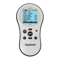
Pressing the Reset button, located on the left side of the Indoor Controller, will momentarily display the
software part numbers and revision letters for both the Controller's Micro-controller chip and the Power
Center's PPD chip. The Reset button also resets the Micro-controller, but does not remove any programming,
AUX labels, etc. (see chart on Page 16 for list of Part Numbers).
Time/Date Backup: Supplied by 9-volt battery located at Power Center
Programming and Memory Backup: Stored in EEPROM on Power Center PCB, stored indefinitely,
even with no power to unit.
NOTE: A Jandy Service Controller (P.N. 7057)
can be attached out at the Power Center, to review
and/or change programs and equipment settings.
Controller Specifications:
Supply Voltage: 10 VDC
Operating Voltage: 5 VDC
Circuit Activation: Serial Communication
TM
ntr
ll
r
Reset Switch
Access Hole
B
k Vi
w
f
ntr
ll
r
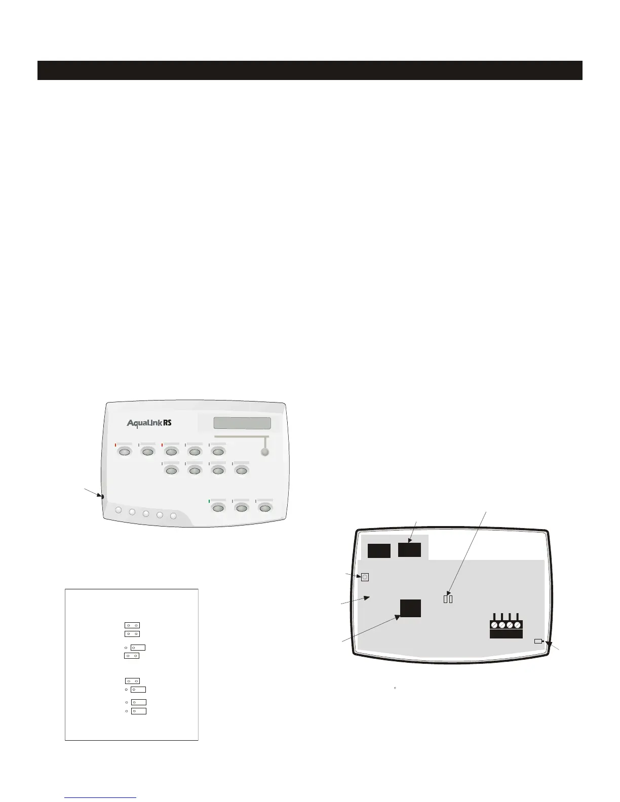
Controller (back view)
Yellow
Green
Black
Red
4321
Delay Override Switch
PCB
Display Module
umpers
or
Multiple Controller
Reset
Switch
Micro Controller
Chart of Multiple Controllers
Jumper Settin
s
Controller 1
W2
W1
Controller 3
W2
W1
Controller 4
W2
W1
W2
Controller 2
W1
AquaLink
®
RS Troubleshooting
1 Controller
2

 Loading...