Pool Temp.
Sensor
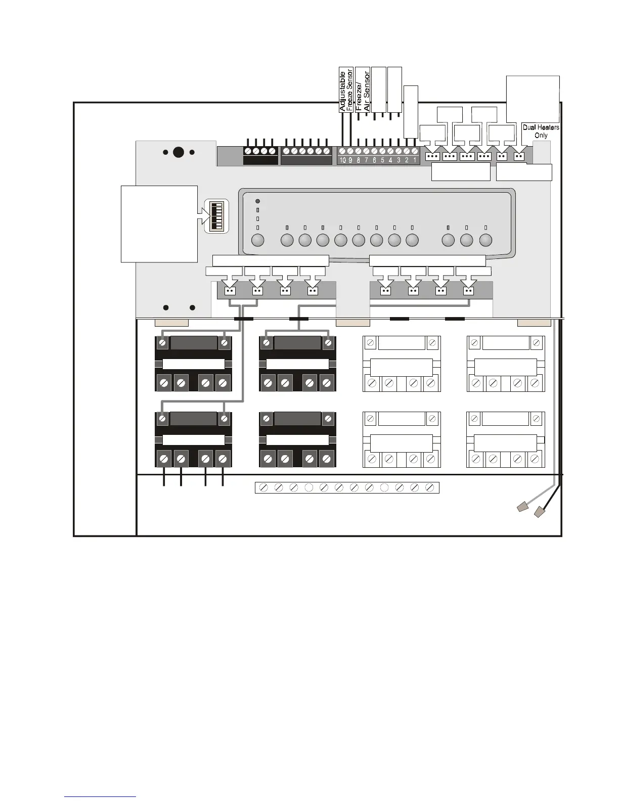
Pool Pump Relay Optional Relay Optional Relay
Optional Relay Optional Relay
Spa Pump Relay
Aux. 1 Relay
Line One
Low Voltage Raceway (do not run high voltage wire in this compartment)
Line Two
Load One
Load Two
Aux. 2 Relay
Grounding Bar
Wire Nut to
120 VAC Power
System Power
Intake
JVA
Cleaner
JVA
Solar
Pump
Return
JVA
Solar
JVA
Spa Heater
Interface
Board
Red
Black
Green
White
Yellow
Green
Black
Red
Brown
To Remote
(brown term. bar)
To Sensors, etc.
(green term. bar)
To Controller
(red term. bar)
4321 654321
Blue
Red
Black
Red
Red
Black
Black
Spa Temp.
Sensor
Pool Low
Voltage Heater
Pool Pump Aux. 1 Aux. 2 Aux. 3
Relay Sockets (24 VDC output)
Spa PumpAux. 6Aux. 5Aux. 4
Relay Sockets (24 VDC output)
Relay Sockets
(24 VDC output)
JVA Sockets
(24 VAC output)
Dip Switches
1 = Cleaner/Aux.1
2 = Low Speed/Aux.2
3 = Not used
4 = Cooldown On/Off
5 = Factory Use
6= Shared Heater
7 = Enable Solar
8 = Heat Pmp/Gas Htr
Batter
9Volt
Wiring Diagram for
AquaLink RS Dual Equipment RS2/6, 2/10, 2/14
21

 Loading...