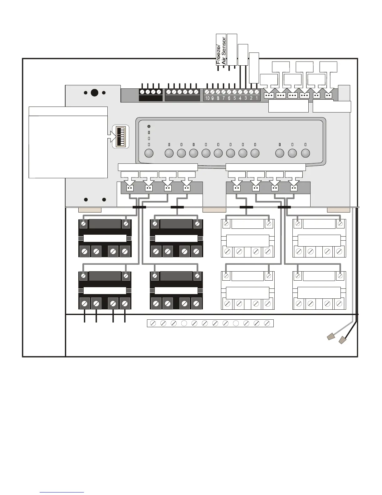
Wiring Diagram for
AquaLink RS Combos and Onlys RS4, 6, 8, 12, 16
Water Temp.
Sensor
Filter Pump Relay
Optional Relay
RS6 or RS8
Optional Relay
RS8
Optional Relay
RS6 or RS8
Optional Relay
RS8
Aux. 3 Relay
Aux. 1 Relay
Line One
Low Voltage Raceway (do not run high voltage wire in this compartment)
Line Two
Load One
Load Two
Aux. 2 Relay
Groundin
Bar
Wire Nut to
120 VAC Power
System Power
Intake
JVA
Cleaner
JVA
Solar
Pump
Return
JVA
Solar
JVA
Elect.
Heater
Red
Black
Green
White
Yellow
Green
Black
Red
Brown
To Remote
(brown term. bar)
To Sensors, etc.
(green term. bar)
To Controller
(red term. bar)
4321 654321
Blue
Red
Not Used
Black
Not Used
Red
Black
Solar
Sensor
Low Voltage
Heater
F.Pump Aux. 1 Aux. 2 Aux. 3
Relay Sockets (24 VDC output)
Aux. 7Aux. 6Aux. 5Aux. 4
Relay Sockets (24 VDC output)
Relay Sockets
(24 VDC output)
JVA Sockets
(24 VAC output)
Batter
(9Volt)
#
1
2
3
4
5
6
7
8
Factory Set
OFF
Aux 1
1 spd pump
Aux 3
Cool Down
See Manual
Not Used
See Manual
Gas Heater
Optional Set
ON
Cleaner
2 spd pump
Spa Spillover
Disabled
See Manual
Not Used
See Manual
Heat Pump
Dip Switch Settin
s
22

 Loading...