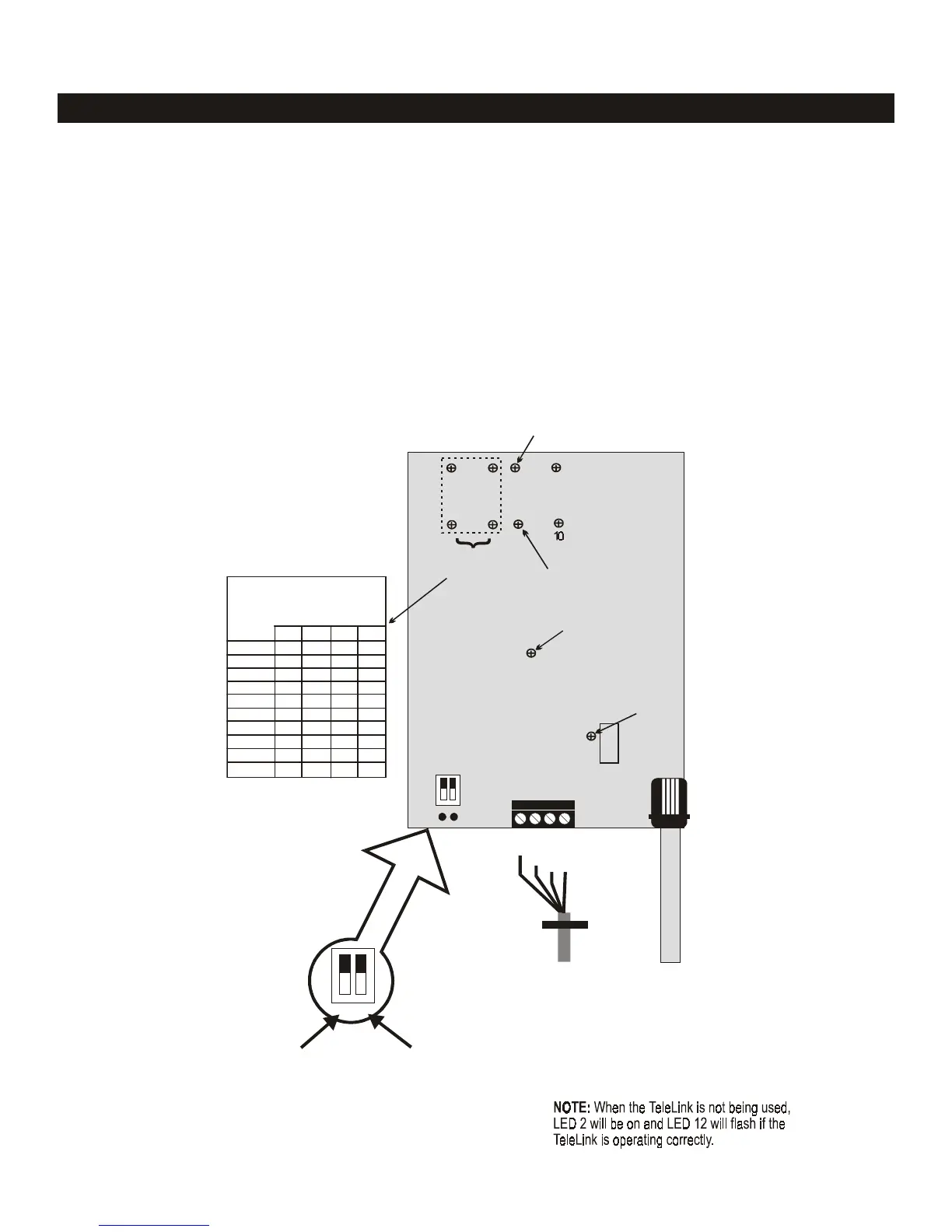
There are two DIP switches on the TeleLink printed circuit board. DIP switch 1 allows the number of rings before
the TeleLink "picks up" to be set, and DIP switch 2 allows the access code to be changed from the factory default (62).
To change either setting, turn on the DIP switch for the item you wish to change (its LED will light). Next, go to a touch-
tone telephone on the same phone line, lift the receiver and press the button or buttons corresponding to the desired
change (e.g., turn on DIP switch 2 and press telephone buttons 7 and 5 to change access code to 75). Finally, replace
the receiver and turn off the DIP switch. The new setting will now be turned into a memory chip.
The TeleLink printed circuit board has a number of LEDs on it. These LEDs help to identify problems with either the
telephone or the TeleLink (see diagram below). When the TeleLink is operating correctly, LED 2 will be on and LED 12
will be flashing. The four LEDs in the upper left hand corner (5, 6, 7 and 8) indicate whether the TeleLink is receiving the
correct pulse when a button is pressed on the telephone key pad. For example, pressing button 4 on a telephone should
light LED 7. Follow the chart to determine other button/LED operations.
The Diagnostics section of the AquaLink RS menu will indicate if the TeleLink is communicating.
Operation
X
X
X X
X
X X
X X
X X X
X
X X
X X
Phone Cable
from Wall Jack
AquaLink RS
TeleLink Board
To RS 485
4-Conductor
Cable
(Cable between
Controller and
Power Center)
red
black
yellow
green
Pro
ram
# of rin
s
(default: 7)
Pro
ram
access code
(default: 62)
12
8
7
6
Key Code
LEDs
LED flashin
- system communication
K
Second di
it of Access Code accepted
First di
it of Access Code accepted
Rings
Access
5
LEDs Lit
®
5
6
78
LEDs
Phone
Key
LED li
hts up when TeleLink
answers incomin
call
LED
oes off when phone rin
s
LED li
hts when button on phone is pressed
1
2
3
4
5
6
7
8
9
0
®
12
11
9
22
1
The chart below indicates
the LED that should li
ht
when a button on the
Telephone Key Pad is
pressed, if theTeleLink is
receivin
the correct si
nal.
AquaLink
®
RS Troubleshooting
TeleLink
12

 Loading...