Page 8
AquaLink
®
Touch™ and Operation Installation Manual
Section 3. Wired AquaLink
Touch
Installation
The AquaLink Touch controller can be used in addition
to an already existing AquaLink RS control system,
however, the firmware in the power center must be
updated to revision Q or later.
3.1 Wired AquaLink Touch AC Adapter
Kit
The Wired AquaLink Touch adapter kit contains the
following items:
Plastic Bag
RS485 Interface Board
Bracket Assembly
AC Adapter
3.2 Installation of the Wired AquaLink
Touch AC Adapter Kit on the Bezel
Assy
WARNING
Potentially high voltages in the AquaLink RS power
center can create dangerous electrical hazards,
possibly causing death, serious injury or property
damage. Turn off power at the main circuit feeding
the AquaLink RS power center to disconnect the
power center from the system.
1. Turn off all power to the power center.
2. Remove the screws that secure the front panel.
Remove the front panel.
3. Unscrew and remove the power center PCB and
bezel assembly from the power center.
4. Unplug the AquaLink RS transformer 24 VAC
power plug from the 24 VAC 3-pin terminal on the
power center as shown in Figure 8.
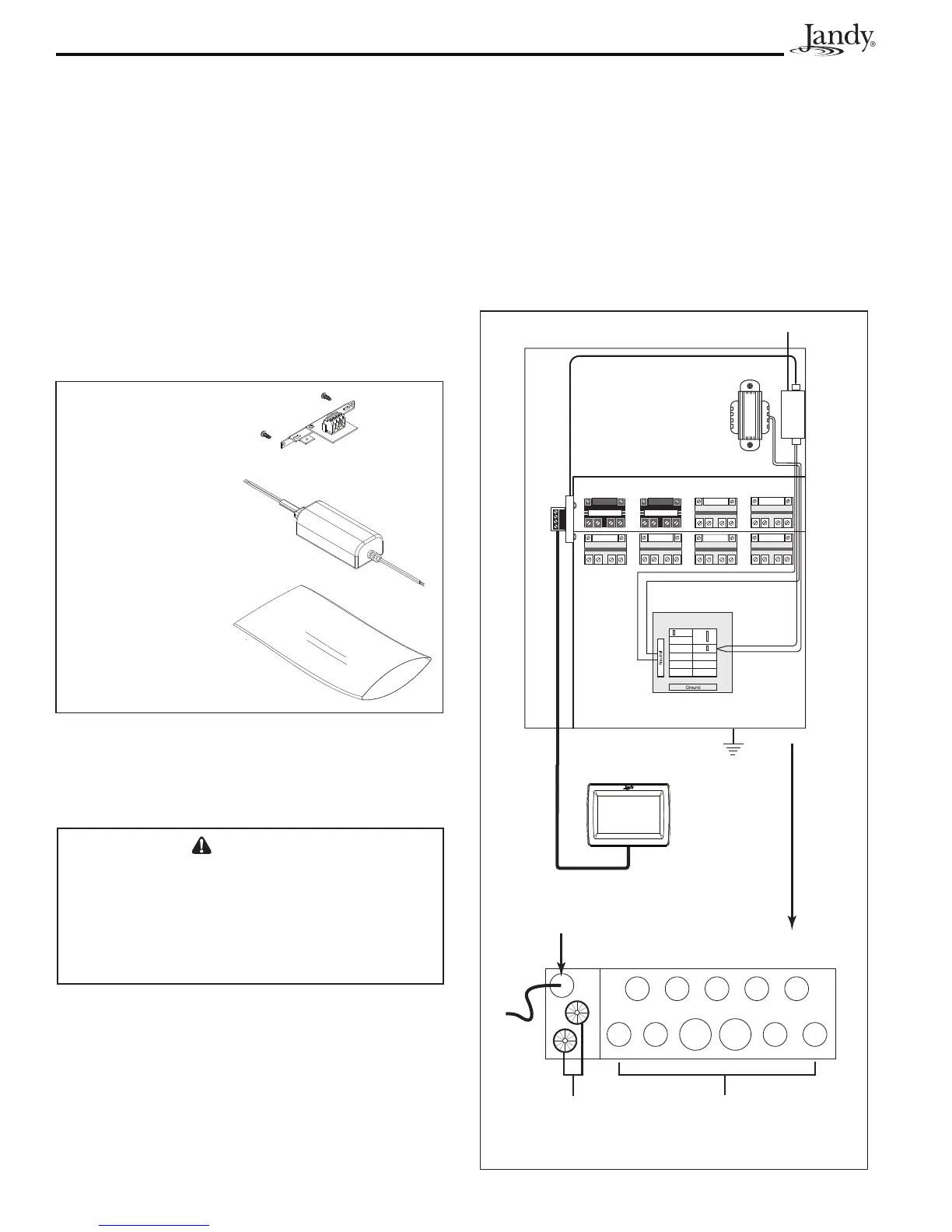
Bottom side of Power Center
Wired
AquaLink Touch
Controller
High Voltage Knockouts
for Conduit (DO NOT run
any Low Voltage wires
through these knockouts)
Heyco Fittings
for Low Voltage
Wires
Low Voltage Conduit
for AquaLink Touch Cable
24VAC
120VAC
AQUALINK RS
POWER TRANSFORMER
AC Adapter
High Voltage
Low Voltage Raceway
4321
Breaker Panel
5. Pull the white and black wires of the AC Adapter
into the high voltage area through the wire conduit.
NOTE The AC adapter and the power center
transformer will share the breaker panel
terminals. See Figure 7.
6. In the high voltage area of the power center,
connect the white wire of the AC adapter to the
neutral bar and the black wire to the circuit breaker
with the AquaLink RS transformer.
Figure 6. Wired AquaLink Touch AC Adapter Kit
Figure 7. Wiring in the Power Center High Voltage Area