Page 12
ePump
™
Series Pumps, Installation and Operation Manual
2. Remove the cover of the ePump junction box and
feed the RS-485 cable into the fitting.
3. Unplug the RS-485 connector from the ePump and
attach the four (4) wires in the RS-485 cable to
the RS-485 connector. Match the wire colors with
the connector positions as follows: 1-red, 2-black,
3-yellow, and 4-green. See Figure 3.
5. Insert the RS-485 connector back into the ePump.
6. Slide dip switches 1 and 2 down, so they are in the
OFF position. See Figure 3.
7. Select the desired address(es) for the ePump(s)
by setting dip switches 3 and/or 4, as shown in
Section 3.3, ePump Dip Switch Settings.
8. Connect the other end of the cable to an RS-485
connector on the AquaLink
®
RS (or multiplexer
interface board), matching wire colors with
connector positions, as described in Step 3.
9. Restore power to the ePump and verify the
operation of the controller.
10. Refer to the appropriate manual to operate the
pump: AquaLink
®
RS Owner’s Manual, 6593, or
AquaLink
®
PDA Owner’s Manual, H0572300.
3.3 ePump Dip Switch Settings
As shown in Figures 2 and 3, the 4-position dip
switch is located at the rear of the ePump. This dip
switch serves two (2) functions: it selects the pump
address, and it determines what type of controller will
be used with the pump.
The tables below show the dip
switch settings
.
Switch
1
Switch
2
Controller
OFF OFF AquaLink
®
RS or AquaLink
®
PDA
OFF ON AquaLink
®
RS or AquaLink
®
PDA
ON OFF AquaLink
®
RS or AquaLink
®
PDA
ON ON ePump
Controller (JEP-R)
Switch 3 Switch 4 Pump Address
OFF OFF PUMP 1
OFF ON PUMP 2
ON OFF PUMP 3
ON ON PUMP 4
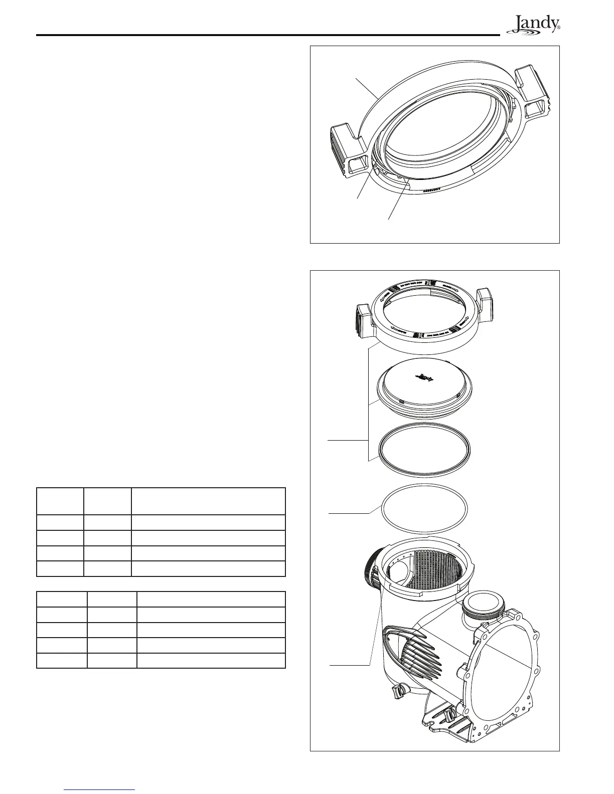
3.4 Pressure Testing
All Jandy model ePumps come with an additional
disposable o-ring for pressure testing. This is the blue
pressure test o-ring. See Figures 4 and 5.
Lid with
Locking
Ring
and
Seal
Blue
Pressure
Test
O-ring
Pump
Debris
Trap
Basket
(Inside
Pump)
Figure 5. Exploded View of Pump
Blue Pressure Test O-ring
Seal
Lid with
Locking
Ring
Figure 4. Blue Pressure Test O-ring in Lid Assembly
 Loading...